1. Introduction
Welcome to the Pi4Micronaut Documentation!
Pi4Micronaut is an Open Source Java library that utilizes the Micronaut Framework and Pi4J to streamline the process of creating custom IoT applications that require hardware connectivity to Raspberry Pi’s.
Pi4Micronaut doesn’t work with the latest Raspberry Pi 5 because of its new architecture. Pi4J and pigpio libraries don’t provide support for Pi 5 yet. Look out for the latest version of Pi4J that will work with Pi 5 in the future.
By reading through our documentation, you will learn how to implement our library into your application.
1.1. How to use the Pi4Micronaut library
This section will walk you through the process of creating a basic Micronaut application and the configuration for developing with Pi4Micronaut. As a demo, this will include the configuration and sample code.
1.1.1. Creating A Micronaut Project
-
Go to Micronaut’s website here.
-
Make sure you have selected Micronaut version 4.7.6 or lower with Java version 17.
-
Click Generate Project and download the zip.
-
Export the contents of the zip file and open it in IntelliJ or any IDE of your choice.
It should look like:

1.1.2. Add Dependency
-
Go to the build.gradle file and find the dependencies.
-
Add the Pi4Micronaut dependency to the list.
implementation("io.github.oss-slu:pi4micronaut-utils:v1.1:all")It should look like:

1.1.3. Setup Configuration
-
Go to the application.yml file and add the configuration of your circuit setup:
path: Demo_Pi4Micronaut/src/main/resources/application.yml
-
Create a new tree in the yml file as shown below.
Note: A BCM numbering system should be used. More info can be found using this link: https://pinout.xyz.
pi4j:
    digital-output:
        led:
            name: LED
            address: 17
            shutdown: LOW
            initial: LOW
            provider: pigpio-digital-output
Here we are specifying a led as a digital output type with name LED, BCM address 17, etc For more information on the LED setup guide, see our documentation here.
It should look like:


1.2. Build and Run the Jar File on Raspberry Pi
This section describes how to build and run the jar file from the Pi4Micronaut project demo on your raspberry pi.
1.2.1. Set up Raspberry Pi OS
-
Start by installing the Raspberry Pi Imager
-
To install the Imager, follow this guide by the Raspberry Pi Foundation here.
Note: use the same wifi network for your raspberry pi that your system is connected to
-
Your configuration should look something like this:


1.2.2. Connecting to Raspberry Pi
-
Get your Raspberry Pi plugged into a power source.
-
You can connect to your Pi several different ways.
-
Using the hostname, for example:
ssh {username}@{hostname}Using our above example configuration:
ssh test@raspberrypi-test -
Using the IP address of your Pi:
Follow the instructions outlined in this article here.
-
1.2.3. Installing Java
-
First, make sure your Raspberry Pi’s package list is up-to-date by running the following commands in your Pi’s terminal:
sudo apt update sudo apt-get upgrade -y -
Next, install Java onto your Pi by running the following command:
sudo apt-get install default-jdk -yTo verify installation, run
java --versionFinally, install pigpio
sudo apt-get install pigpio
1.2.4. Enabling Different Communication Protocols
-
In the Pi4Micronaut library, we have used different communication protocols, such as I2C, SPI, etc.
-
To enable any of these protocols when needed, enter the following command:
sudo raspi-config -
Navigate to "Interfacing Options"

-
Choose your desired protocol.

-
Reboot when prompted.
1.2.5. Build and Copy Over Jar File
-
Open your terminal of choice
-
Navigate to the project root directory
-
Enter the following command into the terminal to build the jar file:
./gradlew build
-
The necessary jar file can be found under "Demo_Pi4Micronaut/build/libs/Demo_Pi4Micronaut-0.1-all.jar"

-
Once you have navigated to this directory, enter the following command:
scp Demo_Pi4Micronaut-0.1-all.jar {username}@{hostname}:~-
Here is an example command, that looks like
scp Demo_Pi4Micronaut-0.1-all.jar test@raspberrypi-test:~
-
1.2.6. Run Jar file on Pi and Test the Application
-
To test if you’ve set up everything correctly on your raspberry pi, we have some sample commands for you to run.
-
Open a new terminal and ssh into your raspberry pi.
-
Enter the following command to run the jar file:
sudo java -jar Demo_Pi4Micronaut-0.1-all.jarThe output should look like this:

With this, a Micronaut localhost server will start running on your machine
-
Let’s test the LED component which you have setup.
-
After getting everything set up, open up a new terminal and ssh into your pi once more.
-
Enter the following command to test the turn on function for an LED light:
curl http://localhost:8080/led/ledOn -
If this command works and the LED has lit up, congratulations! You have successfully built and ran one of our components!
2. Currently Supported Hardware
If you plan on creating an application using any of the hardware components listed below, then our library is perfect for you!
We plan on offering support for many more hardware components in the future. If you have a hardware component you would like to use but can’t find, feel free to checkout how you can add support for it under "Contributing to the Library"
-
4-Digit 7-Segment Display
-
Active Buzzer
-
Fan Controller
-
IR Obstacle Avoidance Sensor
-
LCD1602 (Liquid Crystal Display)
-
LED
-
Micro Switch
-
DC Motor
-
Passive Buzzer
-
PhotoResistor Sensor
-
PIR Motion Sensor
-
Push Button
-
Reed Switch
-
RFID Scanner
-
RGB LED
-
Rotary Encoder
-
Servo Motor
-
Slide Switch
-
Speed Sensor
-
Thermistor Sensor
-
Tilt Switch
-
Touch Switch Sensor
-
Ultrasonic Sensor
3. Contribute to the Pi4Micronaut Library
-
Get Familiar with the Library
-
Before making contributions,understand the purpose and functionality of the Pi4Micronaut library.
-
Review the library documentation, any related articles, or tutorials.
-
-
Set Up Your Development Environment
-
Fork the library’s repository from the GitHub.
-
Clone your fork locally.
-
Follow setup instructions provided in the repository’s README or ADOC files.
-
-
Understand the Contribution Process
-
Familiarize yourself with the library’s contribution guidelines.
-
Understand the community guidelines.
-
Find out the preferred method of communication (e.g., issues, mailing list, discord).
-
-
Identify a Way to Contribute
-
Bug fixes: Look for open issues tagged as 'bug' or report new ones.
-
New features: Discuss new ideas before implementing, to gauge interest and get guidance.
-
Documentation: Contribute to the README, ADOC or other documentation.
-
Testing: Improve or expand the test suite.
-
Refactoring: Optimize existing code or improve its readability.
-
-
Making Changes
-
Always create a new branch for your changes.
-
Follow the library’s coding style and standards.
-
Write clean, well-documented code.
-
Add or update tests for your changes, if necessary.
-
Commit frequently with meaningful commit messages.
-
-
Test Your Changes
-
Ensure that all tests pass.
-
Manually test your changes for unforeseen issues.
-
Ensure your changes do not introduce regressions.
-
Use your own hardware to test the new component integration.
-
Note: A test suite will be developed in future to test the components without the use of external hardware
-
-
Signing the Contributor License Agreement
-
While creating a pull request, you’ll be prompted to sign a Contributor License Agreement. Please do so by logging in with your GitHub account.
-
-
Submit a Pull Request (PR)
-
Push your changes to your forked repository. Create a pull request from your branch to the main library’s main branch.
-
In the PR description, explain your changes, motivations, and any decisions made.
-
Link to any related issues or discussions.
-
-
Respond to Feedback
-
Maintainers or other contributors might provide feedback. Be open to suggestions and make necessary revisions.
-
Engage in a constructive dialogue to ensure the quality of the contribution.
-
-
Stay Updated
-
Keep your fork synchronized with the main repository to ease future contributions.
-
Regularly check for updates or changes in the library’s contribution guidelines.
-
-
Engage with the Community
-
Attend community meetings or join chat groups.
-
Help other contributors or users when you can.
-
Note: While your contribution is highly valued, there’s no guarantee that all pull requests will be merged. It depends on the library’s direction, quality of the contribution, and decisions of the maintainers.
-
Thanks for considering a contribution to the Pi4Micronaut library! Your involvement helps make the project better for everyone.
3.1. How to Create a New Component
If its compatible with a Raspberry Pi then it should work well with the Pi4Micronaut. The following steps should encompass how most components are added to the library. Start by creating a new Issue to suggest changes.
-
Determine the communication type for the component which you want to use. For example, Buzzer works with PWM and LCD1602 works with I2C.
-
Setup the circuit.
-
Add Component to the Application yml
-
The new component will need to be added to the application yml found at
components/src/main/resources/application.yml. -
More information on the
application.ymlfound in Communicating with a Hardware Component
-
-
Create a Helper:
-
A Helper is what the Controller calls to do an action. For example, to change the color of an RGB LED the controller will take the request to change it. The Controller will then call the change color method in the helper. The helper then takes all the actions needed to change the color of the LED.
-
See the RBG Helper for an example of a Helper.
-
All Helpers should be kept here:
pi4micronaut-utils\src\main\java\com\opensourcewithslu\(inputdevices or outputdevices)
-
-
Create a Controller:
-
Controllers define and handle interactions with a given component. The Controller of a component will have a
@Controller("/example")right above the class declaration that acts as the endpoint for requests to the component. Instead of "example", you should name the endpoint something that is identifiable to the component. Each method of the Controller should have a@Get("/exampleEndPoint")above the method declaration. The endpoint for the method should have the same name as the method and any parameters should be included in the endpoint/exampleEndPoint/{parameter1},{parameter2}. -
See the RGB Controller for an example of a Controller.
-
Consult the Micronaut Documentation for more explanation on Controllers.
-
All Controllers should be kept here:
components\src\main\java\com\opensourcewithslu\components\controllers
-
-
Thoroughly test:
-
Contributors should thoroughly test their integrations
-
When submitting a pull request, make sure to include how you tested the component, any circuits that you may have used, and how to run any examples you may have created.
-
It is important that reviewers are able to replicated your work in order to properly test the implementation.
-
-
Create documentation for the component:
-
Create an .adoc file with the component name as the file name.
-
Make sure to include all the information that the other components. Simply copy/paste an existing components documentation and edit as needed.
-
Add the file here:
pi4micronaut-utils/src/docs/asciidoc/componentsunder either input or output components.
-
4. Components
4.1. Communicating with a Hardware Component
Interacting with a hardware component is done through its communication type which determines its circuit setup and configuration.
For example, the LCD1602 component uses an I2C communication type which determines how the circuit is created by utilizing the I2C pins of the GPIO.
Based on the pins and communication type, you have to define the configuration in the yml file accordingly. If a user wants to implement multiple hardware components then the configuration should be defined in the snake yml structure.
Note: A BCM numbering system should be used. More info can be found at https://pinout.xyz.
4.1.1. YAML Configuration Workflow
-
The specifications in the yml file are given to the component in the controller through the use of the @Named() annotation.
-
The controller passes on the configuration to the helper through the object.
-
The communication types are initialized in the Pi4JFactory and Pi4JMultiPinFactory as beans with specifications as listed in the yml file.
-
The communication type configuration classes are in our utilities folder which define the methods and attributes which are used in the factory classes to apply the specifics listed in the yml file.
-
The factory classes create a context with all the beans which can be used by the different hardware components.
-
When the JAR file is ran on the RaspberryPi, the beans interact with the pigpio library to communicate with the GPIO pins.

4.1.2. Digital Input
"Digital Input" refers to a type of electronic signal or data that can be read by the Raspberry Pi’s GPIO pins. These signals are binary, meaning they can only be in one of two states: HIGH (1) or LOW (0).
A BCM numbering system is used. More info can be found here.
To define in application.yaml add digital-input as a field under Pi4J, then add each component under digital-input.
Each component will need
-
name: Name of the component
-
address: GPIO BCM pin associated with component
-
debounce: value that determines the threshold for noise from the component
-
pull: Either PULL_UP or PULL_DOWN depending on component
-
provider: pigpio-digital-input
  digital-input:
    photo-resistor-input:                 (1)
      name: Photo Resistor Input          (2)
      address: 4                          (3)
      debounce: 100000                    (4)
      pull: PULL_DOWN                     (5)
      provider: pigpio-digital-input      (6)
    button-input-1:
      name: Push Button Input
      address: 16
      pull: PULL_DOWN
      debounce: 30
      provider: pigpio-digital-input
    button-input-2:
      name: Push Button Input
      address: 21
      pull: PULL_DOWN
      debounce: 30
      provider: pigpio-digital-input
    button-input-3:
      name: Push Button Input
      address: 18
      pull: PULL_DOWN
      debounce: 30
      provider: pigpio-digital-input
    slide-switch-input:
      name: Slide Switch Input
      address: 18
      pull: PULL_DOWN
      debounce: 3000
      provider: pigpio-digital-input
    slide-switch-input-2:
      name: Slide Switch Input
      address: 22
      pull: PULL_DOWN
      debounce: 3000
      provider: pigpio-digital-input
    touch-switch-input:
      name: Touch Switch Input
      address: 17
      pull: PULL_DOWN
      debounce: 200000
      provider: pigpio-digital-input
    micro-switch:
      name: Micro Switch
      address: 19
      pull: PULL_DOWN
      debounce: 200000
      provider: pigpio-digital-input
    pir-sensor:
      name: PIR Sensor
      address: 13
      pull: PULL_DOWN
      debounce: 30000
      provider: pigpio-digital-input
    ultra-sonic-echo:
      name: UltraSonic Sensor Input
      address: 24
      pull: PULL_DOWN
      debounce: 3000
      provider: pigpio-digital-input
    tilt-switch-input:
      name: Tilt Switch Input
      address: 17
      pull: PULL_DOWN
      debounce: 5000
      provider: pigpio-digital-input
    speed-sensor:
      name: Speed Sensor           (1)
      address: 17                 (2)
      pulses-per-revolution: 20    (3)
      provider: pigpio-digital-input (4)
      debounce: 500                (5)
    adc-dout:
      name: ADC DataOut
      address: 8                # <4> Specify the GPIO pin for Data Out
      pull: PULL_DOWN           # Configure pull-up or pull-down as needed
      debounce: 100             # Optional debounce time for stable readings
      provider: pigpio-digital-input
    reed-switch-input:
      name: Reed Switch
      address: 17
      pull: PULL_UP
      debounce: 200
      provider: pigpio-digital-input
    ir-obstacle-input:
      name: IR Obstacle Avoidance Sensor
      address: 17
      pull: PULL_UP
      debounce: 10000
provider: pigpio-digital-input| 1 | Component Identifier (Used in @Named annotations) |
| 2 | Component Name |
| 3 | Address of connected GPIO pin |
| 4 | Debounce value |
| 5 | Pull value (PULL_UP or PULL_DOWN) |
| 6 | Provider (pigpio-digital-input) ==== Digital Output |
"Digital Output" refers to a signal sent from the Raspberry Pi’s GPIO pins to another device or circuit. Unlike digital input, which the Raspberry Pi reads, digital output is a signal that the Raspberry Pi sends out.
Digital outputs are also binary, meaning they can only have two states: HIGH (1) or LOW (0). These states correspond to different voltage levels, typically 3.3V for high and 0V (ground) for low on a Raspberry Pi.
A BCM numbering system is used. More info can be found here.
To define in application.yaml, add digital-output as a field under Pi4J, then add each component under digital-output.
Each component will need
-
name: Name of the component
-
address: GPIO BCM pin associated with component
-
initial: Initial value, either LOW or HIGH
-
shutdown: State to take when program successfully shuts down properly, either LOW or HIGH
-
provider: pigpio-digital-output
  digital-output:
    led:                                    (1)
      name: LED Output                      (2)
      address: 17                           (3)
      shutdown: LOW                        (4)
      initial: LOW                         (5)
      provider: pigpio-digital-output       (6)
    led2:
      name: LED Output
      address: 26
      shutdown: HIGH
      initial: HIGH
      provider: pigpio-digital-output
    led3:
      name: LED Output
      address: 22
      shutdown: LOW
      initial: HIGH
      provider: pigpio-digital-output
    led4:
      name: LED Output
      address: 27
      shutdown: HIGH
      initial: HIGH
      provider: pigpio-digital-output
    photo-resistor-output:
      name: Photo Resistor Output
      address: 27
      shutdown: LOW
      initial: HIGH
      provider: pigpio-digital-output
    ultra-sonic-trig:
      name: UltraSonic Sensor Output
      address: 23
      shutdown: LOW
      initial: LOW
      provider: pigpio-digital-output
    motor-pin-1:
      name: Motor Pin 1
      address: 17
      shutdown: HIGH
      initial: HIGH
      provider: pigpio-digital-output
    motor-pin-2:
      name: Motor Pin 2
      address: 27
      shutdown: LOW
      initial: LOW
      provider: pigpio-digital-output
    name: Digit 0
    adc-cs:
      name: ADCChipSelect
      address: 5                # <1> Specify the GPIO pin for CS (Chip Select)
      initial: HIGH             # Initial state for Chip Select (could be HIGH or LOW based on needs)
      provider: pigpio-digital-output
    adc-clk:
      name: ADCClock
      address: 6                # <2> Specify the GPIO pin for CLK (Clock)
      initial: LOW              # Initial state for Clock
      provider: pigpio-digital-output
    adc-din:
      name: ADCDataIn
      address: 7                # <3> Specify the GPIO pin for Data In
      initial: LOW              # Initial state for Data In
    digit-0:
      name: Digit 0
      address: 17
      shutdown: LOW
      initial: LOW
      provider: pigpio-digital-output
    digit-1:
      name: Digit 1
      address: 27
      shutdown: LOW
      initial: LOW
      provider: pigpio-digital-output
    digit-2:
      name: Digit 2
      address: 22
      shutdown: LOW
      initial: LOW
      provider: pigpio-digital-output
    digit-3:
      name: Digit 3
      address: 10
      shutdown: LOW
      initial: LOW
      provider: pigpio-digital-output
    sdi:
      name: SDI
      address: 24
      shutdown: LOW
      initial: LOW
      provider: pigpio-digital-output
    rclk:
      name: RCLK
      address: 23
      shutdown: LOW
      initial: LOW
      provider: pigpio-digital-output
    srclk:
      name: SRCLK
      address: 18
      shutdown: LOW
      initial: LOW
provider: pigpio-digital-output| 1 | Component Identifier (Used in @Named annotations) |
| 2 | Component Name |
| 3 | Address of connected GPIO BCM pin |
| 4 | Value to have on shutdown (HIGH = Off, LOW = On) |
| 5 | Value to have on startup |
| 6 | Provider (pigpio-digital-output) ==== I2C |
I2C stands for Inter-Integrated Circuit. It is a bus interface connection protocol incorporated into devices for serial communication. (Source: geeksforgeeks.com) The I2C protocol uses two wires: SDA (serial data) and SCL (serial clock). This protocol allows for communication between multiple devices using only two wires and unique addresses.
A BCM numbering system is used. More info can be found here.
The I2C LCD1602 consists of a normal LCD1602 and an I2C module that is attached to the back of the LCD. The I2C module is a chip that can expand the I/O ports of the LCD1602 using the I2C protocol. It converts the signals from the Raspberry Pi into commands for the LCD.
To define in application.yaml add i2c as a field under pi4j, then add each component under i2c.
Each component will need:
-
name: Name of the component
-
bus: Bus address of device
-
device: BCM Address of device
  i2c:
    lcd:                                  (1)
      name: lcd                           (2)
      bus: 1                              (3)
device: 0x27 (4)| 1 | Component Identifier (Used in @Named annotations) |
| 2 | Component Name |
| 3 | Device bus (0 or 1) |
| 4 | BCM Device address |
4.1.3. MultiPin Configurations
MultiPin components are unique in that they require several of the same type of pin in order to function properly. Each class of multi-pin component (Digital Input, PWM), is declared slightly differently in the application.yaml file
A BCM numbering system is used. More info can be found here.
  multi-digital-input:                     (1)
    rotary-encoder:                        (2)
      name: Rotary Encoder                 (3)
      addresses: 27,18,17                  (4)
      debounces: 6000,500,500              (5)
      pulls: PULL_DOWN,PULL_UP,PULL_UP     (6)
      shutdown: LOW                        (7)
      initial: HIGH                        (8)
      provider: pigpio-digital-input       (9)
    rotary-encoder-2:
      name: Rotary Encoder 2
      addresses: 12, 16, 20
      debounces: 6000, 500, 500
      pulls: PULL_DOWN, PULL_UP, PULL_UP
      shutdown: LOW
      initial: HIGH
provider: pigpio-digital-input| 1 | Top level field for multi-pin digital inputs (equivalent of digital-output declaration) |
| 2 | Component Identifier (Used in @Named annotations) |
| 3 | Component Name |
| 4 | BCM Addresses for each pin (Each component has a specific order outlined in the component description) |
| 5 | Debounce values for each pin (same order as above) |
| 6 | Pull values for each pin (same order as above) |
| 7 | Shutdown value (All pins have the same shut down) |
| 8 | Startup value (All pins have the same start-up) |
| 9 | Provider (All pins have the same provider) |
  multi-pwm:
    rgb-led:                                    (1)
      name: RGB LED                             (2)
      addresses: 17, 18, 27                     (3)
      pwmTypes: SOFTWARE, SOFTWARE, SOFTWARE    (4)
      provider: pigpio-pwm                      (5)
      initials: 0, 0, 0                         (6)
      shutdowns: 0, 0, 0                        (7)
    rgb-led-2:
      name: RGB LED 2
      addresses: 18, 27, 22
      pwmTypes: SOFTWARE, SOFTWARE, SOFTWARE
      provider: pigpio-pwm
      initials: 0, 0, 0
shutdowns: 0, 0, 0| 1 | Top level field for multi-pin PWMs |
| 2 | Component Identifier (Used in @Named annotations) |
| 3 | Component Name |
| 4 | BCM Addresses for each pin (Each component has a specific order outlined in the component description) |
| 5 | PWM types for each pin (same order as above) |
| 6 | Provider (All pins have the same provider) |
| 7 | Startup values (Same order as above) |
| 8 | Shutdown values (Same order as above) ==== PWM |
Pulse width modulation, or PWM, is a technique for getting analog results with digital means. Digital control is used to create a square wave, a signal switched between on and off. This on-off pattern can simulate voltages in between full on (5 Volts) and off (0 Volts) by changing the portion of the time the signal spends on versus the time that the signal spends off. The duration of “on time” is called the pulse width. To get varying analog values, you change, or modulate, that pulse width (Source: sunfounder.com). In our library, our Active Buzzer component uses PWM. Once fully activated at 5 Volts, the buzzer will go off, creating a tone.
To define in application.yaml add pwm as a field under pi4j, then add each component under pwm.
A BCM numbering system is used. More info can be found here.
Each component will need:
-
name: Name of the component
-
BCM address: GPIO pin associated with component
-
pwmType: Either SOFTWARE or HARDWARE based upon which type of PWM you wish to use
-
provider: pigpio-pwm
-
initial: Initial value on startup
-
shutdown: Final value at shut down
  pwm:
    active-buzzer:               (1)
      name: active-buzzer        (2)
      address: 17                (3)
      pwmType: SOFTWARE          (4)
      provider: pigpio-pwm       (5)
      initial: 0                 (6)
      shutdown: 0                (7)
    passive-buzzer:
      name: passive-buzzer
      address: 17
      pwmType: SOFTWARE
      provider: pigpio-pwm
      initial: 0
      shutdown: 0
    servo-motor:
      name: Servo Motor
      address: 18
      pwmType: SOFTWARE
      provider: pigpio-pwm
      initial: 0
      shutdown: 0
    motor:
      name: Motor
      address: 22
      pwmType: SOFTWARE
      provider: pigpio-pwm
      initial: 0
      shutdown: 0
    fan:
      name: FAN
      address: 18
      pwm-type: SOFTWARE
      provider: pigpio-pwm
      initial: 0
shutdown: 0| 1 | Component Identifier (Used in @Named annotations) |
| 2 | Component Name |
| 3 | BCM Address of connected GPIO pin |
| 4 | PWM Type (HARDWARE or SOFTWARE) |
| 5 | Provider (pigpio-digital-output) |
| 6 | Value to have on start up |
| 7 | Value to have on shut down |
4.1.4. SPI
The Serial Peripheral Interface (SPI) is a communication protocol used to transfer data between the Raspberry Pi and peripheral devices. These peripheral devices may be either sensors or actuators.
Many different devices use the SPI protocol, such as SD card reader modules, RFID card reader modules, and 2.4 GHz wireless transmitter/receivers all use SPI to communicate with the Raspberry Pi.
SPI uses 4 separate connections to communicate with the target device:
-
COPI (Controller Output/Peripheral Input) – Line for the Controller to send data to the Peripherals.
-
CIPO (Controller Input/Peripheral Output) – Line for the Peripherals to send data to the Controller.
-
SCLK (Clock) – Line for the clock signal.
-
PS/CS (Peripheral Select/Chip Select) – Line for the Controller to select which Peripheral to send data to.
Note: Controller/Peripheral is formerly referred to as Master/Slave. In order to move away from the use of such terminology, we have opted to use the term Controller in place of Master, and Peripheral in place of Slave.
A BCM numbering system is used. More info can be found here.
To define in application.yaml add spi as a field under pi4j, then add each component under spi.
Each component will need:
-
name: Name of the component
-
BCM address: Address for Controller/Peripheral
-
baud: Baud rate/data rate
-
reset-pin: Address of GPIO reset pin
  spi:
    rfid:                   (1)
      name: MFRC522         (2)
      address: 8            (3)
      baud: 500000          (4)
      reset-pin: 25         (5)
    adc0834: # Configuration for ADC0834
      name: ADC0834  (1)
      address: 17            # <2> # SPI channel 0
      baud: 1000000         # <3> # 1 MHz SPI clock speed
reset-pin: 27| 1 | Component Identifier (Used in @Named annotations) |
| 2 | Component Name |
| 3 | BCM Address of GPIO Reset pin |
| 4 | Baud rate |
4.2. Input Components
The Components that provide input signal or data to the application from Raspberry Pi GPIO pins. :imagesdir: img/
4.2.1. Micro Switch
Overview
This section provides details of a Micro Switch implementation, including its circuit diagram, schematic diagram, required hardware components, assembly instructions, and functionality.
Components
-
1 x Micro switch
-
2 x LEDs of different colors
-
2 x 220Ω resistor
-
1 x 10kΩ resistor
-
1 x 10⁴ Capacitor
-
Breadboard
-
Jumper wires
Assembly Instructions
-
Place the micro switch on the breadboard. Connect the common terminal 'C' to GPIO17.
-
Connect the common terminal 'C' terminal of the micro switch to the ground via a 10KΩ resistor.
-
Place the 0.1 µF capacitor (104) across the switch terminals directly on the breadboard. Connect one side to the GPIO17 where the switch connects and the other side to the ground via the other end of 10KΩ resistor which was connected to micro switch’s 'C' terminal. This capacitor serves as a debouncing element, smoothing out any electrical noise caused by the physical action of the switch.
-
Connect the Normally Open 'NO' terminal of the micro switch to the ground (GND). This resistor acts as a pull-down, ensuring the switch input reads LOW when not pressed.
-
Connect the Normally Closed 'NC' terminal directly to the +3.3V power supply. This means when the switch is not pressed, the GPIO pin will be held HIGH through this connection.
-
Insert the two LEDs onto the breadboard, ensuring the longer leg (anode) is towards the positive supply and the shorter leg (cathode) towards the ground.
-
Connect a 220Ω resistor to the anode of each LED and the other end of these resistors to a positive voltage supply (+3.3V).
-
Connect the cathodes of the LEDs. GPIO22 for LED1 and GPIO27 for LED2.
-
Connect the positive voltage supply (+3.3V) to the positive rail of the breadboard and link the ground (GND) to the negative rail. Ensure all ground connections of the components are tied to this rail.
See the circuit diagram below for more detail.


Functionality
A Micro Switch is a small, very sensitive switch that requires minimum compression to activate. Because they are reliable and sensitive, micro switches are often used as a safety device. When the micro switch in your circuit is pressed, it breaks the connection between the Common 'C' terminal and the Normally Closed 'NC' terminal, which is linked to +3.3V, and instead makes a connection between the Common terminal and the Normally Open 'NO' terminal, connected to ground through a 10KΩ pull-down resistor. This change pulls the GPIO17 pin to a LOW state. Assuming your microcontroller is programmed accordingly, this action can be used to trigger specific behaviors, such as turning on an LED connected to another GPIO pin. This setup utilizes the micro switch to easily control electronic components through simple physical interaction.
Testing the Circuit
Use the below commands to test the micro switch.
-
/enable- turns on micro switch
$ curl http://localhost:8080/microSwitch/enable
-
/disable- turns off micro switch
$ curl http://localhost:8080/microSwitch/disable
Troubleshooting
-
LEDs do not light up once it has been enabled and the micro switch is pressed:
-
Make sure that the correct GPIO pins are being used for the LEDs and Micro Switch as specified in the yml.
-
Confirm that everything is properly secured to the breadboard and is receiving power.
-
Ensure that the micro switch and all resistors are correctly placed according to the schematic.
-
Look for any unintended short circuits on the breadboard, particularly around the areas where the switch and LEDs are connected.
-
Ensure that the capacitor (0.1 µF) is properly placed across the correct terminals of the micro switch
-
Ensure a 220Ω is being used for the LEDs and 10kΩ resistor for the Micro Switch.
-
YAML Configuration
A BCM numbering system is used. More info can be found here.
The YAML configuration for the LEDs is as follows:
digital-output:
  led1:
    name: LED Output
    address: 22
    shutdown: HIGH
    initial: HIGH
    provider: pigpio-digital-output

    led2:
    name: LED Output
    address: 27
    shutdown: HIGH
    initial: HIGH
    provider: pigpio-digital-output
So, the output of the LEDs is connected to GPIO 22 and GPIO 27 respectively.
The YAML configuration for the micro switch is as follows:
    micro-switch:
      name: Micro Switch
      address: 17
      pull: PULL_DOWN
      debounce: 200000
      provider: pigpio-digital-input
So, the input of the micro switch is connected to GPIO 17.
Constructor and Methods
To see the constructor and methods of our MicroSwitchHelper class see our javadoc here for more details.
An Example Controller
This controller uses the micro switch to light up LED2 once it is pressed and LED1 if it is not pressed.
@Controller("/microSwitch")
public class MicroSwitchController {
    private static final Logger log = LoggerFactory.getLogger(MicroSwitchController.class);
    private final MicroSwitchHelper microSwitchHelper;
    private final LEDHelper ledHelper1;
    private final LEDHelper ledHelper2;

    public MicroSwitchController(@Named("micro-switch") DigitalInput microSwitch,
                                 @Named("led") DigitalOutput led1,
                                 @Named("led2") DigitalOutput led2) {
        this.microSwitchHelper = new MicroSwitchHelper(microSwitch);
        this.ledHelper1 = new LEDHelper(led1);
        this.ledHelper2 = new LEDHelper(led2);
    }

    //enables the micro switch. The LEDs will switch states as the switch is pressed
    @Get("/enable")
    public void enableMicroSwitch() {
        microSwitchHelper.addEventListener(e -> {
            try {
                if (microSwitchHelper.isPressed) {
                    ledHelper1.ledOff();
                    ledHelper2.ledOn();
                } else {
                    ledHelper1.ledOn();
                    ledHelper2.ledOff();
                }
            } catch (Exception ex) {
                log.error("Error switching LED state", ex);
            }
        });
    }

    //disable the micro switch
    @Get("/disable")
    public void disableMicroSwitch() {
        microSwitchHelper.removeEventListener();
    }
}
4.2.2. PhotoResistor Sensor
Overview
This section provides the details of the PhotoResistor Sensor including its components, assembly instructions, and functionality.
Components
-
1 x RaspberryPi
-
1 x Breadboard
-
1 x LED
-
1 x PhotoResistor Sensor
-
1 x 220Ω Resistor
-
1 x Capacitor (10µf)
-
2 x 10KΩ Resistor
-
4 Jumper Wires
-
Power source
Assembly Instructions
-
Place the PhotoResistor onto the breadboard.
-
Place the LED onto the breadboard with the Cathode pin in the negative side of the breadboard. The Anode pin will be placed onto the main section of the breadboard.
-
Place a 220Ω resistor next to the anode pin of the LED, then place the other pin in line on the main section of the breadboard.
-
Place one side of the Capacitor onto the negative side of the breadboard.
-
Place the other side of the Capacitor into the breadboard inline with a jumper wire and a 10KΩ Resistor.
-
Place the PhotoResistor Sensor onto the breadboard inline with the Capacitor, 10KΩ Resistor. The PhotoResistor should have a 10KΩ pin on either side of its' pins.
-
The 10KΩ resistor pin should then be placed in line away from the PhotoResistor pins.
-
Place a jumper wire from GND pin to the negative side of the board.
-
Place a jumper wire from GPIO4 next to the positive pin of the Capacitor and the 10KΩ Resistor.
-
Place a jumper wire from GPIO17 and place it next to the 220Ω Resistor
-
Place a jumper wire from GPIO27 to the pin of the 10KΩ.

Functionality
PhotoResistor is a DigitalInput and DigitalOutput type that controls the LED’s behavior based on changes in light intensity.
Testing
Use the below command to test the component.
$curl http://localhost:8080/photoResistor/enable-
/enable- Initializes the PhotoResistor
$curl http://localhost:8080/photoResistor/getDarkness-
/getDarkness- returns the darkness level
$curl http://localhost:8080/photoResistor/disable-
/disable- Disables the photoresistor
$curl http://localhost:8080/photoResistor/threshold/i-
/threshold/{i}- Sets the threshold for the darkness.
Troubleshooting
LED not lighting:
-
Verify that the appropriate resistors are being used (220Ω)
-
Double check the power source
PhotoResistor not working:
-
Ensure that the darkness level is appropriately set
-
Verify the PhotoResistor is correctly placed into the breadboard
-
Verify the correct resistor is used (10KΩ)
YAML Configuration
A BCM numbering system is used. More info can be found here.
The PhotoResistor as it appears in the YAML file:
  digital-input:
    photo-resistor-input:                 (1)
      name: Photo Resistor Input          (2)
      address: 4                          (3)
      debounce: 100000                    (4)
      pull: PULL_DOWN                     (5)
      provider: pigpio-digital-input      (6)

  digital-output:
    photo-resistor-output:
      name: Photo Resistor Output
      address: 27
      shutdown: LOW
      initial: HIGH
      provider: pigpio-digital-output
Constructor and Methods
To see the constructor and methods of the PhotoResistorHelper class see our java doc here for more details.
Example Controller
This controller sets up the photoresistor sensor
@Controller("/photoResistor")
public class PhotoResistorController {
    private static final Logger log = LoggerFactory.getLogger(PhotoResistorController.class);
    private final LEDHelper ledHelper;
    private final PhotoResistorHelper photoResistorHelper;

    public PhotoResistorController(@Named("photo-resistor-input")DigitalInput photoResistorIN,
                                   @Named("photo-resistor-output")DigitalOutput photoResistorOUT,
                                   @Named("led")DigitalOutput led ) {
        this.photoResistorHelper = new PhotoResistorHelper(photoResistorIN, photoResistorOUT);
        this.ledHelper = new LEDHelper(led);

    }

    @Get("/enable")
    public int enableLightSensor(){
        photoResistorHelper.initialize();
        photoResistorHelper.addEventListener(e -> {
            try {
                if (photoResistorHelper.isDark) {
                    ledHelper.ledOn();
                } else {
                    ledHelper.ledOff();
                }
            } catch (Exception ex) {
                log.error("Error switching LED state", ex);
            }
        });
        return photoResistorHelper.getDark();

    }

    @Get("/getDarkness")
    public int dark() {
        return photoResistorHelper.getDark();
    }

    @Get("/disable")
    public void disableLightSensor() {
        photoResistorHelper.removeEventListener();
    }

    @Post("/threshold/{i}")
    public String setThreshold(@Positive int i) {
        photoResistorHelper.setDarknessThreshold(i);
        return ("Darkness threshold set to "+ i + "\n");
    }

}
4.2.3. PIR Sensor
Overview
This section provides details of the PIR Sensor, including the components and assembly instructions. A Passive Infrared Sensor measures infrared light radiating from objects to detect motion.
Components
-
PIR Sensor
-
Breadboard
-
T-Extension Board
-
Jumper wires x 3
-
Power source (5V)
-
3 x 220Ω resistors
-
RGB LED
Assembly Instructions
When looking at the bottom of PIR, the pins from left to right are:
-
Power: connect the left pin on the PIR to 5V0 on the breadboard
-
I/O: connect the middle pin on the PIR to GPIO 13 on the breadboard
-
Ground: connect right pin on the PIR to GND on the breadboard
-
Set up the RGB LED

Functionality
A PIR - Passive Infrared sensor detects motion by sensing changes in the infrared light emitted by objects in its environment. It works passively, meaning it does not emit any infrared light itself, but rather detects the infrared radiation coming from warm objects, such as humans or animals. The sensor has two sensitive slots that detect infrared radiation.
As a warm object moves across its field of view, the amount of infrared radiation reaching each slot changes, creating a detectable change in the radiation pattern. This change triggers the sensor to send an electrical signal, which can then be used to activate alarms, lights, or other devices, making PIR sensors widely used in security systems and automated lighting controls due to their efficiency and effectiveness in detecting motion.
Testing
Use the below command to enable the sensor.
$ curl http://localhost:8080/pirSensor/enableOnce the sensor is enabled, anytime the sensor detects motion, the RGB LED will turn red. If no motion is detected, the RGB LED will be green.
Use the below command to disable the sensor.
$ curl http://localhost:8080/pirSensor/disableTroubleshooting
-
Sensor not detecting something:
-
Make sure the object is moving. The sensor only detects movement. Once an object stops moving, it is no longer detected.
-
YAML Configuration
A BCM numbering system is used. More info can be found here.
digital-input:
    pir-sensor:
      name: PIR Sensor
      address: 13
      pull: PULL_DOWN
      debounce: 30000
      provider: pigpio-digital-input
Constructor and Methods
The constructor and the methods within the PIRSensorHelper class can be seen in our javadoc here.
Example Controller
This controller uses the PIR Sensor to turn an RGB LED red if motion is detected, green otherwise
@Controller("/pirSensor")
public class PIRSensorController {
    private final PIRSensorHelper pirSensorHelper;
    private final RGBLEDHelper rgbledHelper;
/**
* The PirSensorController constructor.
* @param pirSensor A Pi4J DigitalInput object.
* @param rgbLed A MultiPinConfiguration object.
*/
public PIRSensorController(@Named("pir-sensor") DigitalInput pirSensor, @Named("rgb-led-2") MultiPinConfiguration rgbLed) {
this.pirSensorHelper = new PIRSensorHelper(pirSensor);
this.rgbledHelper = new RGBLEDHelper(rgbLed);
}
/**
 * Enables the PIR sensor by adding an event listener which sets the RGB LED to red when movement is detected and green otherwise.
 */
@Get("/enable")
public void enablePIRSensor() {
    int[] red = {255,0,0};
    int[] green = {0,255,0};
    pirSensorHelper.addEventListener(e -> {
        if (pirSensorHelper.isMoving) {
            rgbledHelper.setColor(red);
        }
        else {
            rgbledHelper.setColor(green);
        }
    });
}
    /**
     * Disables the controller by removing the event listener and turning off the RGB LED.
     */
    @Get("/disable")
    public void disablePIRSensor() {
        pirSensorHelper.removeEventListener();
        rgbledHelper.ledOff();
    }
}
==== Push Button
Overview
This document provides details of the Push Button circuit, including its components, assembly instructions, and functionality.
Components
-
LED light
-
Push button
-
1 x 10Ω resistor
-
1 x 220Ω resistor
-
Breadboard
-
Jumper wires
-
Power source
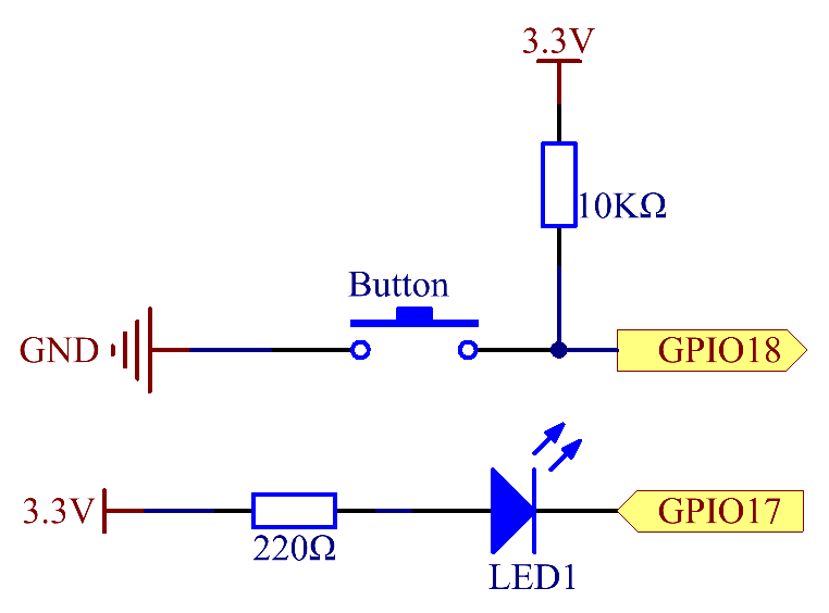
Circuit Diagram
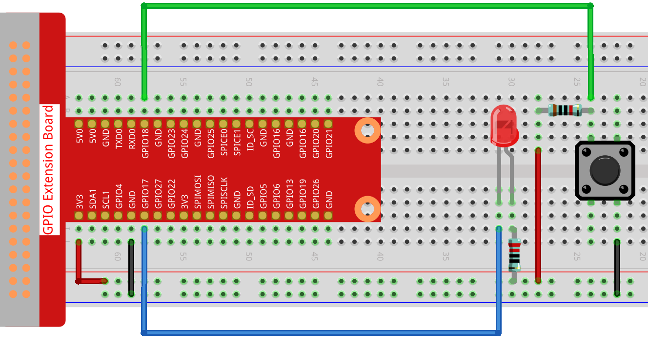
Schematic Diagram:
Testing
Use below command to test the component.
$ curl http://localhost:8080/pushButton/init-
/init- Initializes the Push Button for use.
Troubleshooting
-
LED not lighting up: Check all connections, ensure the LED is placed correctly, and check the power source.
-
LED is too dim: The resistor value might be too high. Ensure you’re using the correct resistors or adjust according to your power source and LED specifications
YAML Configuration
A BCM numbering system is used. More info can be found here.
The order for declaring the pin for the LED is as follows:
digital-output:
  led:
    name: LED Output
    address: 17
    shutdown: LOW
    initial: LOW
    provider: pigpio-digital-output
So the LED would be connected to GPIO 17.
The order for declaring the pin for the push button is as follows:
digital-input:
    button-input-3:
      name: Push Button Input
      address: 18
      pull: PULL_DOWN
      debounce: 30
      provider: pigpio-digital-input
So the push button would be connected to GPIO 18.
Constructor and Methods
To see the constructor and methods of our PushButtonHelper class see our javadoc here for more details.
An Example Controller
This controller uses the push button to turn an LED on and off
@Controller("/pushButton")
public class PushButtonController {
    private static final Logger log = LoggerFactory.getLogger(PushButtonController.class);
    private final PushButtonHelper pushButtonHelper;
    private final LEDHelper ledHelper;

    public PushButtonController(@Named("button-input-3") DigitalInput pushButton,
                                @Named("led") DigitalOutput led) {
        this.pushButtonHelper = new PushButtonHelper(pushButton);
        this.ledHelper = new LEDHelper(led);
    }

    @Get("/init")
    public void initController(){
        pushButtonHelper.addEventListener(e ->{
            if(pushButtonHelper.isPressed){
                try {
                    ledHelper.switchState();
                } catch (Exception ex) {
                    log.error("Failed to switch LED state.", ex);
                }
            }
        });
    }
}
4.2.4. Reed Switch
Overview
This document describes a reed (magnetic) switch sensor implementation: required hardware, assembly instructions, circuit diagrams, configuration, and testing. A reed switch is a small magnetic sensor that closes a contact when a magnet is brought near.
Components
-
Reed switch module
-
2 x LED lights
-
2 x 220Ω resistors
-
Breadboard
-
Jumper wires
-
Power source (3.3V)
Assembly Instructions
Connect the reed switch, LEDs, resistors, and wiring on the breadboard as shown in the circuit diagrams.
-
Ground: connect the GND pin of the reed switch to the breadboard ground.
-
Power: connect VCC of the reed switch to 3.3V on the breadboard.
-
IO: connect the reed switch output pin (DO) to GPIO 17 on the Raspberry Pi (digital input).
-
LEDs: use a 220Ω resistor in series with each LED. Connect the LED cathodes to ground and the anodes to the GPIO outputs.
-
LED GPIOs: connect the two LED anodes to GPIO 22 and GPIO 27 respectively (digital outputs).


Functionality
When a magnet approaches the reed switch the internal contacts change state (close). In our example controller we read this digital input and drive one LED for detection and another for no detection.
Testing the Circuit
Use the following HTTP endpoints to interact with the reed switch controller.
-
/enable- enable reed switch handling
$ curl http://localhost:8080/reedSwitch/enable
-
/disable- disable reed switch handling
$ curl http://localhost:8080/reedSwitch/disable
Troubleshooting
-
LED does not light when expected:
-
Verify VCC and GND are correctly wired and the breadboard power rail is powered.
-
Ensure LEDs are oriented correctly (anode to resistor → GPIO, cathode to GND).
-
Confirm resistors are 220Ω.
-
Check the reed switch wiring: DO connected to GPIO 17, VCC to 3.3V, GND to ground.
-
-
False triggers or bouncing:
-
Verify the configured pull-up/pull-down and debounce values in YAML.
-
Move wires away from noisy power lines; shorten jumper wires where possible.
-
YAML Configuration
A BCM numbering system is used. More info can be found here.
The YAML configuration for the reed switch input:
digital-input:
  reed-switch-input:
    name: Reed Switch
    address: 17
    pull: PULL_UP
    debounce: 200
    provider: pigpio-digital-input
The YAML configuration for the first LED:
digital-output:
  led3:
    name: LED Output
    address: 22
    shutdown: LOW
    initial: HIGH
    provider: pigpio-digital-output
The YAML configuration for the second LED:
digital-output:
  led4:
    name: LED Output
    address: 27
    shutdown: HIGH
    initial: HIGH
    provider: pigpio-digital-output
Constructor and Methods
To see the constructor and methods of the ReedSwitchHelper class see the javadoc: https://oss-slu.github.io/Pi4Micronaut/javadoc/com/opensourcewithslu/inputdevices/ReedSwitchHelper.html
An Example Controller
This controller uses the reed switch to light up LED lights when activated
@Controller("/reedSwitch")
public class ReedSwitchController {
    private final Logger log = LoggerFactory.getLogger(ReedSwitchController.class);
    private final ReedSwitchHelper reedSwitchHelper;
    private final LEDHelper ledHelper3;
    private final LEDHelper ledHelper4;

    public ReedSwitchController(@Named("reed-switch-input") DigitalInput reedSwitch,
                              @Named("led3") DigitalOutput led3,
                              @Named("led4") DigitalOutput led4) {
        this.reedSwitchHelper = new ReedSwitchHelper(reedSwitch);
        this.ledHelper3 = new LEDHelper(led3);
        this.ledHelper4 = new LEDHelper(led4);
    }

    @Get("/enable")
    public void enableReedSwitch() {
        reedSwitchHelper.addEventListener(e -> {
            try {
                if (reedSwitchHelper.isDetected) {
                    ledHelper3.ledOn();
                    ledHelper4.ledOff();
                } else {
                    ledHelper3.ledOff();
                    ledHelper4.ledOn();
                }
            } catch (Exception ex) {
                log.error("Error switching LED state", ex);
            }
        });
    }

    @Get("/disable")
    public void disableReedSwitch() {
        reedSwitchHelper.removeEventListener();
    }
}
4.2.5. RFID Scanner
Overview
This section provides information regarding the RFID scanner component and its circuit, including assembly instructions.
Assembly Instructions
-
Put RFID scanner on breadboard as shown in the diagram below.
-
Connect the RFID ground to the ground on the Pi, and connect the 3.3V pin of the RFID scanner to the 3V3 pin of the Pi.
-
Connect the rest of the RFID pins to the corresponding pins on the Pi.

Functionality
RFID Scanner requires RFID tags to work with. We can read/write the data on to the tags using the scanner.
-
/write/{value}- Writes {value} to the RFID key fob -
/read- Scanner will be ready to read the key fob
Testing the Circuit:
To write to the RFID fob:
$ curl -X POST http://localhost:8080/rfid/write/HelloThereScan the key fob to write the message to the fob.
To read from the RFID fob:
$ curl http://localhost:8080/rfid/readScan the key fob and the message on the fob will be printed.
HelloThereYAML Configuration
A BCM numbering system is used. More info can be found here.
The RFID scanner configuration as it appears in the application.yml:
spi:
   rfid:
      name: MFRC522
      address: 8
      baud: 500000
      reset-pin: 25
Constructors and Methods
To see the constructor and methods of our RFidHelper class see our javadoc here for more details.
An Example Controller
This controller uses the RFID scanner to write and read to a card
@Controller("/rfid")
public class RfidController {
    private final RFidHelper rfidHelper;

    public RfidController(@Named("rfid") SpiConfig spi, Context pi4jContext){
        this.rfidHelper = new RFidHelper(spi, 25, pi4jContext);
    }

    @Post("/write/{value}")
    public void writeToCard(String value){
        rfidHelper.writeToCard(value);
    }

    @Get("/read")
    public String readFromCard(){
        Object data = rfidHelper.readFromCard();
        return data.toString();
    }
}
4.2.6. Rotary Encoder
Overview
This section provides details of the Rotary Encoder circuit, including its components, assembly instructions, and functionality.
Assembly Instructions
Connect the 5 pins on the encoder to the breadboard along with the resistor as stated below and in the diagram.
-
Ground: Connect ground on the encoder to ground on the breadboard
-
Power: Connect the + on the encoder to the 3.3V on the breadboard
-
SW: Connect SW to GPIO 27 on the breadboard
-
DT: Connect DT to GPIO 17 on the breadboard
-
CLK: Connect CLK to GPIO 18 on the breadboard
-
Resistor: Place the resistor horizontally so that it is parallel with GPIO 27, having one side on the red + with the other next to the wire on GPIO 27
-
Connect a wire from 3.3V to the red + in the same column as the resistor

Testing the Circuit
To return the value of the rotary encoder:
$ curl http://localhost:8080/rotaryEncoder/value-
/value- returns the current value of the rotary encoder
Troubleshooting
-
Value not being returned: Make sure all pins on the encoder match up to the correct GPIO pins according to the YAML pin order below.
-
Make sure that a 10k resistor is being used
YAML Configuration
A BCM numbering system is used. More info can be found here.
The order for declaring pins for a Rotary Encoder component in the application.yaml file is as follows
SW-PIN-INFO, CLK-PIN-INFO, DT-PIN-INFO
So in the case of
multi-digital-input:
  rotary-encoder:
    name: Rotary Encoder
    addresses: 27,18,17
    debounces: 6000,500,500
    pulls: PULL_DOWN,PULL_UP,PULL_UP
    shutdown: LOW
    initial: HIGH
    provider: pigpio-digital-input
the sw pin would be the one connected to GPIO 27, the clk pin would be connected to GPIO 18, and the dt pin would connect to GPIO 17. All lists of values for Rotary Encoder components will follow the same order.
Constructors and Methods
To see the constructor and methods of our RotaryEncoderHelper class see our javadoc here for more details.
An Example Controller
This controller uses a rotary encoder
@Controller("/rotaryEncoder")
public class RotaryEncoderController {
    private final RotaryEncoderHelper encoderHelper;

    public RotaryEncoderController(@Named("rotary-encoder") MultiPinConfiguration rotaryEncoder){
        this.encoderHelper = new RotaryEncoderHelper(rotaryEncoder);
    }

    @Get("/value")
    public int getEncoderValue(){return encoderHelper.getEncoderValue();}
}
4.2.7. Slide Switch
Overview
This section provides the details of the Slide Switch circuit, including its components, assembly instructions, and functionality.
Components
-
Slide Switch
-
1 x 10Ω resistor
-
1 x Capacitor 104
-
Breadboard
-
7 x Jumper Wires
-
Power source (appropriate voltage, typically 3.3V or 5V)
Assembly Instructions
-
Place the slide switch and the capacitor vertically in the same column on the breadboard.
-
Connect the middle pin of the slide switch to the bottom pin of the capacitor.
-
Place the resistor so that one side is in the same row as the middle pin of the slide switch with the wire from step two between, and the other side to the top pin of the resistor.
-
Power the slide switch by connecting the 5V pin from the pin to the positive column of the breadboard and connecting the bottom pin of the slide switch to that column.
-
Connect the top pins of the slide switch and the capacitor to the negative column of the breadboard. Connect the GND pin of the Pi to that column.
-
Connect the GPIO18 pin of the Pi to the middle pin of the slide switch so that the resistor and the connection to the capacitor are between.

Functionality
Making a request to the switch will return whether the switch is on or off, flip the switch to change the state.
Testing the Circuit:
Use the below command to test the switch.
$ curl http://localhost:8080/slideSwitch/switch1This will either return true,if the switch is on, and false if the switch is off. Flip the switch and run the command again to see the opposite result of the first call.
Troubleshooting
Verify that all connections are correct and that the order of components in a row are correct.
YAML Configuration
A BCM numbering system is used. More info can be found here.
The slide switch as it appears in the application.yml:
digital-input:
    slide-switch-input:
      name: Slide Switch Input
      address: 18
      pull: PULL_DOWN
      debounce: 3000
      provider: pigpio-digital-input

    slide-switch-input-2:
      name: Slide Switch Input
      address: 22
      pull: PULL_DOWN
      debounce: 3000
      provider: pigpio-digital-input
Note: There are two slide switches, one that uses GPIO 18 and the other uses GPIO 22.
Constructors and Methods
To see the constructor and methods of our SlideSwitchHelper class see our javadoc here for more details.
An Example Controller
This controller sets up two slide switches
@Controller("/slideSwitch")
public class SlideSwitchController {
    private final SlideSwitchHelper slideSwitchHelper;
    private final SlideSwitchHelper slideSwitchHelper2;

    public SlideSwitchController(@Named("slide-switch-input")DigitalInput slideSwitch,
                                    @Named("slide-switch-input-2")DigitalInput slideSwitch2) {
        this.slideSwitchHelper = new SlideSwitchHelper(slideSwitch);
        this.slideSwitchHelper2 = new SlideSwitchHelper(slideSwitch2);
    }

    @Get("/switch1")
    public boolean checkSwitch1(){
        return slideSwitchHelper.isOn;
    }

    @Get("/switch2")
    public boolean checkSwitch2(){
        return slideSwitchHelper2.isOn;
    }
}
4.2.8. Speed Sensor
Overview
This section provides the details of the Speed Sensor circuit, including its components, assembly instructions, and functionality.
Components
-
Speed Sensor
-
Bread Board
-
T-Extension Board
-
7x Jumper Cables
-
Green LED Light Bulb
-
Red LED Light Bulb
-
2x 220Ω Resistors
-
Power source
Assembly Instructions
-
Ground (GND): Connect the GND pin on the speed sensor to the ground rail on the breadboard.
-
VCC: Connect the VCC pin on the speed sensor to the 5V pin on the Raspberry Pi GPIO header via the breadboard power rail.
-
Digital Output (D0): Connect the D0 pin on the speed sensor to GPIO 17 (Pin 11) on the Raspberry Pi GPIO header.
-
Connect the longer leg (anode) of the red LED to a row on the breadboard.
-
Place a 220-ohm resistor between the shorter leg (cathode) of the red LED and the ground rail on the breadboard.
-
Use a jumper wire to connect the same row as the anode of the red LED to GPIO 27 (Pin 13) on the Raspberry Pi.
-
Similarly, place the green LED on the breadboard.
-
Connect the longer leg (anode) to a free row.
-
Place another 220-ohm resistor between the cathode of the green LED and ground.
-
Use a jumper wire to connect the anode of the green LED to GPIO 22 (Pin 15).
-
Connect the ground rail on the breadboard to a ground pin (GND) on the Raspberry Pi GPIO header (e.g., Pin 6).
-
Connect the power rail on the breadboard to a 5V pin on the Raspberry Pi GPIO header (e.g., Pin 2).


Testing the Circuit:
Use the below command to test the speed sensor.
$curl http://localhost:8080/speedSensor/enable-
/enable- Initializes the Speed Sensor
$curl http://localhost:8080/speedSensor/speed/rpm-
/speed/rpm- Returns the speed in RPM
$curl http://localhost:8080/speedSensor/speed/disable-
/disable- Disables the Speed Sensor
Troubleshooting
Verify that all connections are correct and that the order of components in a row are correct.
YAML Configuration
A BCM numbering system is used. More info can be found here.
The speed sensor as it appears in the application.yml:
digital-input:
  speed-sensor:
    name: Speed Sensor
    address: 17
    pulses-per-revolution: 20
    provider: pigpio-digital-input
    debounce: 500
Constructors and Methods
To see the constructor and methods of our SpeedSensorHelper class see our javadoc here for more details.
An Example Controller
This controller sets up Speed Sensor
@Controller("/speedSensor")
public class SpeedSensorController {

    private final SpeedSensorHelper speedSensorHelper;

    public SpeedSensorController(@Named("speed-sensor-pin") DigitalInput sensorPin, @Named("pulsesPerRevolution") double pulsesPerRevolution) {
        this.speedSensorHelper = new SpeedSensorHelper(sensorPin, pulsesPerRevolution);
    }

    /**
     * Enables the speed sensor and starts measuring speed.
     */
    @Get("/enable")
    public String enableSpeedSensor() {
        this.speedSensorHelper.startMeasuring();
        return "Speed Sensor Enabled";
    }

    /**
     * Returns the speed in RPM.
     */
    @Get("/speed/rpm")
    public String getSpeedInRPM() {
        return this.speedSensorHelper.getRPM() + " RPM\n";
    }

    /**
     * Disables the speed sensor.
     */
    @Get("/disable")
    public String disableSpeedSensor() {
        this.speedSensorHelper.stopMeasuring();
        return "Speed Sensor Disabled";
    }
}
4.2.9. Thermistor Sensor
Overview
This section provides details of the Thermistor, including the components and assembly instructions.
Components
-
Thermistor
-
Breadboard
-
T-Extension Board
-
ADC0834 Analog to Digital Converter
-
Jumper wires x 16
-
Power source (5V)
-
10KΩ resistor
Assembly Instructions
-
Insert the ADC0834 chip into the breadboard with its pins centered around the central divider
-
Connect VCC (pin 16) of ADC0834 to the 5V pin on the Raspberry Pi GPIO.
-
Connect GND (pin 8) to the GND pin on the Raspberry Pi GPIO.
-
CLK (pin 18): Connect to the (GPIO18) pin on the Raspberry Pi.
-
DOUT (pin 27): Connect to the (GPIO27) pin on the Raspberry Pi.
-
DIN (pin 27): Connect to the (GPIO10) pin on the Raspberry Pi.
-
CS (pin 17): Connect to the (GPIO17) pin on the Raspberry Pi.

Functionality
A Thermistor - A thermistor is a thermally sensitive resistor that exhibits a precise and predictable change in resistance proportional to small changes in temperature.
Testing
Use the below command to get Fahrenheit.
$ curl http://localhost:8080/temperature/fahrenheitUse the below command to get Celsius.
$ curl http://localhost:8080/temperature/celsiusTroubleshooting
-
Sensor not detecting something:
-
Make sure the pins of the thermistor are in the correct pins of ADC0834 *
-
Constructor and Methods
The constructor and the methods within the ThermistorHelper class can be seen in our javadoc here.
4.2.10. Tilt Switch
Overview
This section provides details of a tilt switch implementation, including its circuit diagram, required hardware components, assembly instructions, and functionality.
Components
-
Tilt switch module
-
LED light
-
1 x 220Ω resistor
-
1 x 1kΩ resistor
-
Breadboard
-
Jumper wires
-
Power source
Assembly Instructions
-
Ground: Place the ground so that it is connected to the tilt switch and the LED
-
Power: Place the power (3.3V) so that power is given to both the LED and tilt switch
-
Resistor (220Ω): Place the 220Ω resistor vertically so that it can connect the LED light to power
-
Resistor (1kΩ): Place the 1kΩ resistor vertically so that it can provide power to the tilt switch
-
Connect a wire from GPIO26 to the LED which is its digital output
-
Attach a wire from GPIO17 to the tilt switch which is its digital input
See the circuit diagram below for more detail.


Functionality
When the tilt switch is tilted or its orientation is changed, a metal ball moves inside the capsule and opens or closes an electrical circuit, altering the state of the switch. Our example showcases a tilt switch and LED which lights up when the tilt switch is enabled and detects a change in orientation.
Testing the Circuit
Use the below commands to test the tilt switch.
-
/enable- turns on tilt switch
$ curl http://localhost:8080/tiltSwitch/enable
-
/disable- turns off tilt switch
$ curl http://localhost:8080/tiltSwitch/disable
Troubleshooting
-
LED not lighting up once it has been enabled and is being tilted:
-
Make sure that the correct GPIO pins are being used for the LED and Tilt Switch as specified in the yml.
-
Confirm that everything is properly secured to the breadboard and is receiving power.
-
Ensure a 220Ω is being used for the LED and 1kΩ resistor for the Tilt Switch.
-
YAML Configuration
A BCM numbering system is used. More info can be found here.
The YAML configuration for the LED is as follows:
digital-output:
  led2:
    name: LED Output
    address: 26
    shutdown: HIGH
    initial: HIGH
    provider: pigpio-digital-output
So, the output of the LED is connected to GPIO 26.
The YAML configuration for the tilt switch is as follows:
digital-input:
  tilt-switch-input:
    name: Tilt Switch Input
    address: 17
    pull: PULL_DOWN
    debounce: 5000
    provider: pigpio-digital-input
So, the input of the tilt switch is connected to GPIO 17.
Constructor and Methods
To see the constructor and methods of our TiltSwitchHelper class see our javadoc here for more details.
An Example Controller
This controller uses the tilt switch to light up a LED light once it is tilted
@Controller("/tiltSwitch")
public class TiltSwitchController {
    private static final Logger log = LoggerFactory.getLogger(TiltSwitchController.class);
    private final TiltSwitchHelper tiltSwitchHelper; // controls the tilt switch
    private final LEDHelper ledHelper; // controls the LED

    public TiltSwitchController(@Named("tilt-switch-input")DigitalInput tiltSwitch,
                                @Named("led2")DigitalOutput led) {
        this.tiltSwitchHelper = new TiltSwitchHelper(tiltSwitch);
        this.ledHelper = new LEDHelper(led);
    }

    // The 'enable' method adds an event listener that listens for changes in the tilt switch
    // If it is tilted, the LED turns on and off otherwise
    @Get("/enable")
    public void enableTiltSwitch() {
        tiltSwitchHelper.addEventListener(e -> {
            try {
                if (tiltSwitchHelper.isTilted) {
                    ledHelper.ledOn();
                } else {
                    ledHelper.ledOff();
                }
            } catch (Exception ex) {
                log.error("Error switching LED state", ex);
            }
        });
    }

    // The disable method removes the event listener
    @Get("/disable")
    public void disableTiltSwitch() {
        tiltSwitchHelper.removeEventListener();
    }
}
4.2.11. Touch Switch
Overview
This section provides details of a touch switch sensor implementation, including its circuit diagram, required hardware components, assembly instructions, and functionality.
Assembly Instructions
Connect the 3 pins on the touch switch to the breadboard as well as the LED and resistor making sure the LED has power.
-
Ground: connect the ground on the touch switch to the ground on the breadboard
-
Power: Connect the VCC on the touch switch to the 3.3V on the breadboard
-
You will want to have a wire connecting 3.3V and ground to the bottom of the board so that power can be supplied to the LED and touch switch as shown in the diagram below
-
-
IO: Connect the IO on the touch switch to GPIO 17 on the breadboard which is the digital input
-
Resistor: Place the resistor vertically so that it can connect the LED light to power
-
Connect a wire from GPIO26 to the LED which is its digital output


Testing the Circuit
Use the below commands to test the touch switch.
-
/enable- turns on touch switch
$ curl http://localhost:8080/touchSwitch/enable
-
/disable- turns off touch switch
$ curl http://localhost:8080/touchSwitch/disable
Troubleshooting
-
LED not lighting up once it has been enabled and is being touched: Make sure that all the pins on the touch switch are in the right spot and that everything is receiving power. Also make sure that everything is properly secured to the breadboard.
-
Ensure a 220Ω resistor is being used
YAML Configuration
A BCM numbering system is used. More info can be found here.
The YAML configuration for the LED is as follows:
digital-output:
  led2:
    name: LED Output
    address: 26
    shutdown: HIGH
    initial: HIGH
    provider: pigpio-digital-output
So, the output of the LED is connected to GPIO 26.
The YAML configuration for the touch switch is as follows:
digital-input:
  touch-switch-input:
    name: Touch Switch Input
    address: 17
    pull: PULL_DOWN
    debounce: 200000
    provider: pigpio-digital-input
So, the input of the touch switch is connected to GPIO 17.
Constructor and Methods
To see the constructor and methods of our TouchSwitchHelper class see our javadoc here for more details.
An Example Controller
This controller uses the touch switch to light up a LED light once touched
@Controller("/touchSwitch")
public class TouchSwitchController {
    private static final Logger log = LoggerFactory.getLogger(TouchSwitchController.class);
    private final TouchSwitchHelper touchSwitchHelper;
    private final LEDHelper ledHelper;

    public TouchSwitchController(@Named("touch-switch-input") DigitalInput touchSwitch,
                                 @Named("led2") DigitalOutput led) {
        this.touchSwitchHelper = new TouchSwitchHelper(touchSwitch);
        this.ledHelper = new LEDHelper(led);
    }

    @Get("/enable")
    public void enableTouchSwitch() {
        touchSwitchHelper.addEventListener(e -> {
            try {
                if (touchSwitchHelper.isTouched) {
                    ledHelper.ledOn();
                } else {
                    ledHelper.ledOff();
                }
            } catch (Exception ex) {
                log.error("Error switching LED state", ex);
            }
        });
    }

    @Get("/disable")
    public void disableTouchSwitch() {
        touchSwitchHelper.removeEventListener();
    }
}
4.2.12. Ultrasonic Sensor
Overview
This document provides details of the Ultrasonic Sensor circuit, including its components, assembly instructions, and functionality.


Functionality
The Ultrasonic Sensor uses sound waves to calculate the distance from itself to the surface it is pointed at. The resulting measurement is accurate within a range of 3mm of the true measurement. The Ultrasonic Sensor’s signal is stable within 5m of the sensor, gradually weakening until the signal fully disappears at 7m.
Testing
Use the below commands to test the component.
$curl http://localhost:8080/ultraSound/enable-
/enable- turns on ultrasonic sensor, starts measuring distance -
/distance/cm- returns distance to nearest object in centimeters -
/distance/m- returns distance to nearest object in meters -
/disable- turns off ultrasonic sensor
Troubleshooting
-
Distance measurements not showing: Check all connections, ensure the sensor is placed correctly, and check the power source.
YAML Configuration
A BCM numbering system is used. More info can be found here.
The order for declaring the Trigger and Echo Pins of the Ultrasonic Sensor is as follows:
So the Trigger Pin would be connected to GPIO 23 and the Echo Pin would be connected to GPIO 24.
digital-input:
  ultra-sonic-echo:
    name: UltraSonic Sensor Input
    address: 24
    pull: PULL_DOWN
    debounce: 3000
    provider: pigpio-digital-input

digital-output:
  ultra-sonic-trig:
    name: UltraSonic Sensor Output
    address: 23
    shutdown: LOW
    initial: LOW
    provider: pigpio-digital-output
Constructor and Methods
To see the constructor and methods of our UltraSonicSensor class see our javadoc here for more details.
An Example Controller
This controller uses the Ultrasonic Sensor to calculate distance from the sensor to a surface
@Controller("/ultraSound")
public class UltraSonicSensorController {
    private final UltraSonicSensorHelper ultraSonicSensorHelper;

    public UltraSonicSensorController(@Named("ultra-sonic-trig") DigitalOutput trig,
                                      @Named("ultra-sonic-echo") DigitalInput echo) {
        this.ultraSonicSensorHelper = new UltraSonicSensorHelper(trig,echo);

    }

    /**
     * Enables the ultrasonic sensor
     */
    @Get("/enable")
    public String enableUltraSonicSensor() {
        this.ultraSonicSensorHelper.startMeasuring();
        return "Ultra Sonic Sensor Enabled \nIf the distance is constantly Zero, make sure the sensor field of view is clear \n";
    }

    /**
     * Returns distance from object in centimeters
     */
    @Get("/distance/cm")
    public String getDistanceInCentimeter() {
        return this.ultraSonicSensorHelper.getDistanceInCentimeter() + " cm\n";
    }

    /**
     * Returns distance from object in meters
     */
    @Get("/distance/m")
    public String getDistanceInMeter() {
        return this.ultraSonicSensorHelper.getDistanceInMeters() + " m\n";
    }

    /**
     * Disables ultrasonic sensor
     */
    @Get("/disable")
    public String disableUltrasoundSensor() {
        this.ultraSonicSensorHelper.stopMeasuring();
        return "Ultra Sonic Sensor Disabled";
    }
}
4.3. Output Components
The Components that provide output signal either by emitting, displaying, lighting, etc. through Raspberry Pi GPIO pins. :imagesdir: img/
4.3.1. 4-Digit 7-Segment Display
Overview
This section provides details of the 4-digit 7-segment display, including its components and assembly instructions.
Components
-
1 x Raspberry Pi
-
1 x Breadboard
-
1 x T-Extension Board
-
25 x Jumper Wire
-
4 x Resistor (220Ω)
-
1 x 4-Digit 7-Segment Display
-
1 x 74HC595
-
Power source (appropriate voltage, typically 3.3V)
Assembly Instructions
-
Connect the ground (GND) pins of the Raspberry Pi to the ground rails on the breadboard.
-
Connect the two ground rails of the breadboard with a jumper wire.
-
Place the 74HC595 on the breadboard.
-
Place the four resistors on the breadboard.
-
Place the 4-digit 7-segment display on the breadboard.
-
Connect a jumper wire from each "digit" pin of the 4-digit 7-segment to one of the resistors.
-
Connect the other ends of the resistors to the Raspberry Pi’s pins:
-
Digit 1 (pin 12) to GPIO17 (BCM pin 18)
-
Digit 2 (pin 9) to GPIO27 (BCM pin 27)
-
Digit 3 (pin 8) to GPIO22 (BCM pin 22)
-
Digit 4 (pin 6) to SPIMOSI (BCM pin 10)
-
-
Use jumper wires to connect pins on the display to pins on the 74HC595:
-
A (pin 11) to Q0 (pin 15)
-
B (pin 7) to Q1 (pin 1)
-
C (pin 4) to Q2 (pin 2)
-
D (pin 2) to Q3 (pin 3)
-
E (pin 1) to Q4 (pin 4)
-
F (pin 10) to Q5 (pin 5)
-
G (pin 5) to Q6 (pin 6)
-
DP (pin 3) to Q7 (pin 7)
-
-
Use jumper wires to connect the 74HC595 to the Raspberry Pi:
-
SHcp (pin 11) to GPIO18 (BCM pin 18)
-
STcp (pin 12) to GPIO23 (BCM pin 23)
-
DS (pin 14) to GPIO24 (BCM pin 24)
-
-
Use jumper wires to connect the remaining pins of the 74HC595 to the ground rails of breadboard.


Functionality
The display can be enabled/disabled, display a custom value, or cleared.
Each digit of the display can display a digit 0 to 9, an uppercase letter A to F, a hypen (-), or a blank space. Each of the four decimal points can also be turned on or off.
Example possible values include:
-
"1" (displayed with the 1 in the first digit and the others blank)
-
"8.8.8.8." (displayed with all segments enabled as
8.8.8.8.) -
"A.-.42" (displayed as
A.-.42
Testing
Use the below commands to test the component.
The first two commands will cause the display to turn on and display the value 1234.
The third command will cause the display to then show 1.234.
The fourth command will cause the display to show 1 34, using standard URL encoding for the space (%20).
$ curl http://localhost:8080/four-digit-seven-segment/enable
$ curl http://localhost:8080/four-digit-seven-segment/displayValue/1234
$ curl http://localhost:8080/four-digit-seven-segment/set-decimal-point/0/true
$ curl http://localhost:8080/four-digit-seven-segment/displayValue/1%2034-
/enable- Enables the display. -
/disable- Disables the display. -
/print/{value}- Displays a custom value on the display. -
/clear- Clears the display. -
/set-digit/{digit}/{value}- Sets a specific digit to a specific value. -
/set-decimal-point/{digit}/{value}- Sets a specific decimal point to on (true) or off (false).
Troubleshooting
-
Display does not turn on
-
Ensure all connections are secure and correct.
-
Check the 74HC595 for proper orientation and placement.
-
Ensure the software configuration matches the hardware setup.
-
Look for any error messages in the console or logs.
-
-
Display turns on but does not respond to commands
-
Check the software configuration for any discrepancies.
-
Ensure the 74HC595 is functioning properly.
-
YAML Configuration
A BCM numbering system is used. More info can be found here.
digital-output:
  digit-0:
    name: Digit 0
    address: 17
    shutdown: LOW
    initial: LOW
    provider: pigpio-digital-output
  digit-1:
    name: Digit 1
    address: 27
    shutdown: LOW
    initial: LOW
    provider: pigpio-digital-output
  digit-2:
    name: Digit 2
    address: 22
    shutdown: LOW
    initial: LOW
    provider: pigpio-digital-output
  digit-3:
    name: Digit 3
    address: 10
    shutdown: LOW
    initial: LOW
    provider: pigpio-digital-output
  sdi:
    name: SDI
    address: 24
    shutdown: LOW
    initial: LOW
    provider: pigpio-digital-output
  rclk:
    name: RCLK
    address: 23
    shutdown: LOW
    initial: LOW
    provider: pigpio-digital-output
  srclk:
    name: SRCLK
    address: 18
    shutdown: LOW
    initial: LOW
    provider: pigpio-digital-output
Constructor and Methods
To see the constructor and methods of our FourDigitSevenSegmentHelper class see our javadoc here for more details.
An Example Controller
@Controller("/four-digit-seven-segment")
public class FourDigitSevenSegmentDisplayController {
    private final FourDigitSevenSegmentDisplayHelper displayHelper;

    public FourDigitSevenSegmentDisplayController(@Named("sdi") DigitalOutput sdi,
                                                  @Named("rclk") DigitalOutput rclk,
                                                  @Named("srclk") DigitalOutput srclk,
                                                  @Named("digit-0") DigitalOutput digit0,
                                                  @Named("digit-1") DigitalOutput digit1,
                                                  @Named("digit-2") DigitalOutput digit2,
                                                  @Named("digit-3") DigitalOutput digit3) {
        this.displayHelper = new FourDigitSevenSegmentDisplayHelper(sdi, rclk, srclk, digit0, digit1, digit2, digit3);
    }

    @Get("/enable")
    public void enable() {
        displayHelper.enable();
    }

    @Get("/disable")
    public void disable() {
        displayHelper.disable();
    }

    @Get("/print/{value}")
    public void print(String value) {
        displayHelper.print(value);
    }

    @Get("/clear")
    public void clear() {
        displayHelper.clear();
    }

    @Get("set-digit/{digit}/{value}")
    public void setDigit(int digit, char value) {
        displayHelper.setDigit(digit, value);
    }

    @Get("set-decimal-point/{digit}/{value}")
    public void setDecimalPoint(int digit, boolean value) {
        displayHelper.setDecimalPoint(digit, value);
    }
}
4.3.2. Active Buzzer
Overview
This section provides details of the Active Buzzer, including the components and assembly instructions. The Active Buzzer only emits one frequency, as described in the code, to play various sounds.
Components
-
1 x RaspberryPi
-
1 x Breadboard
-
1 x T-extension Board
-
1 x Active Buzzer
-
6 x Jumper wires
-
1 x Resistor (1KΩ)
-
1 x S8550 PNP Transistor
-
Power source (appropriate voltage, typically 3.3V)
Assembly Instructions
-
Place the Active Buzzer onto the Breadboard.
-
Place the 1KΩ resistor onto the Breadboard, must be inline with base pin of S8550 PNP Transistor.
-
Place the S8550 PNP Transistor onto the BreadBoard.
-
The Active Buzzer will have two pins. The longer pin is the anode (+) while the shorter is the cathode(-).
-
Connect a jumper wire from GND to (-) negative side
-
Connect a jumper wire from 3.3V to (+) positive side.
-
Connect a jumper wire from GPIO 17 to the 1KΩ resistor
-
Connect jumper wire from positive side to positive end of Active Buzzer.
-
Connect jumper wire from negative end of Active Buzzer to emitter pin of S8550 PNP Transistor.
-
Connect jumper wire from negative side to collector pin of S8550 PNP Transistor.


Functionality
Active Buzzer is PWM type and emits a beep tone, intermittent tone and a morseCode tone based on the frequency and the time interval.
Note: If you use transistor in the circuit, it swaps the functionalities of the buzzer i.e., if you enable the buzzer, it actually disables it and vice versa.
Testing the circuit
Use the below command to test the component.
$curl http://localhost:8080/active-buzzer/enable-
/enable- Turns the Active Buzzer on.
$curl http://localhost:8080/active-buzzer/disable-
/disable- Turns the Active Buzzer off.
$curl http://localhost:8080/active-buzzer/beepTone-
/beepTone- Emits a beep sound from the Active Buzzer.
$curl http://localhost:8080/active-buzzer/intermittentTone-
/intermittentTone- Emits an intermittent tone from the Active Buzzer. The total duration is twenty seconds: ten seconds of sound and ten seconds of silence.
$curl http://localhost:8080/active-buzzer/morseCode-
/morseCode- Emits the word "pi" in morse code.
Troubleshooting
-
Active Buzzer not creating sound:
-
Double check power source
-
Verify that 1K resistor is used
-
Verify all wires are in appropriate slots.
-
YAML Configuration
A BCM numbering system is used. More info can be found here.
pwm:
  active-buzzer:
    name: active-buzzer
    address: 17
    pwmType: SOFTWARE
    provider: pigpio-pwm
    initial: 0
    shutdown: 0
Constructor and Methods
The constructor and the methods within the ActiveBuzzerHelper class can be seen in our javadoc here.
Example Controller
This controller uses the Active Buzzer to emit sound once prompted by the commands
@Controller("/active-buzzer")
public class ActiveBuzzerController {
    private final ActiveBuzzerHelper activeBuzzerHelper;

    public ActiveBuzzerController(@Named("active-buzzer") Pwm activeBuzzerOutput){
        this.activeBuzzerHelper = new ActiveBuzzerHelper(activeBuzzerOutput);
    }

    /**
     * Enables the active buzzer
     */
    @Get("/enable")
    public void enableActiveBuzzer(){

        activeBuzzerHelper.activeBuzzerOn();

    }

    /**
     * Disables the active buzzer
     */
    @Get("/disable")
    public void disableActiveBuzzer(){

        activeBuzzerHelper.activeBuzzerOff();

    }

    /**
     * Emits a beep sound from the active buzzer.
     */
    @Get("/beepTone")
    public void playBeepTone(){

        activeBuzzerHelper.beep();

    }

    /**
     * Emits an intermittent tone from the active buzzer for a duration of 20 seconds.
     * 10 seconds of sound and 10 seconds of silence
     */
    @Get("/intermittentTone")
    public void playIntermittentTone(){

        activeBuzzerHelper.intermittentTone();

    }

    /**
     * Tests the active buzzer by emitting the word "pi" in morse code.
     */
    @Get("/morseCode")
    public void morseCodeTest(){

        activeBuzzerHelper.morseCodeTone();
    }
}
4.3.3. Fan Controller
Overview
This section provides comprehensive details about the Fan Controller component, covering its configuration, circuit setup, and usage instructions.
Components
-
1 x Raspberry Pi
-
1 x Fan (PWM-controlled or simple DC fan)
-
Jumper wires
-
Breadboard
-
Power source
Circuit Setup
-
Connect the fan to the Raspberry Pi GPIO pins as specified in the YAML configuration.
-
Use a PWM-compatible pin to control the fan speed (if the fan supports PWM).
-
Connect a common ground between the fan and the Raspberry Pi.
-
Refer to the circuit diagram for detailed wiring instructions.


YAML Configuration
A BCM numbering system is used. More info can be found here.
The following YAML configuration is used to set up the Fan Controller in application.yml. This configuration includes parameters to control fan speed and behavior.
  # tag::fan[]
  fan:
    controller:
      name: "Raspberry Pi Fan Controller"
      pwm-pin:
        name: Fan PWM Pin
        address: 18
        frequency: 25000
        shutdown: LOW
        initial: LOW
        provider: pigpio-pwm-output
      speed-settings:
        low: 30
        medium: 60
        high: 100
  # end::fan[]
Functionality
The Fan Controller allows the Raspberry Pi to control the speed of a fan using PWM (Pulse Width Modulation) or simple on/off states. It supports predefined speed levels (e.g., low, medium, high).
Testing
To test the Fan Controller component with the Micronaut API, use the following commands:
$ curl http://localhost:8080/fan/speed/high-
/speed/{level}- Sets the fan speed to the specified level (low,medium, orhigh). -
/stop- Turns off the fan. -
/shutdown- Deactivates the fan completely and resets settings.
4.3.4. IR Obstacle Avoidance Sensor
Overview
This section provides details for the IR Obstacle Avoidance Sensor, including its components, assembly instructions, and functionality.
The IR (Infrared) Obstacle Avoidance Module is a proximity sensor that detects objects and obstacles within a short distance (2-30cm) using infrared reflection. It is commonly used in robotics for collision avoidance, object detection, and boundary sensing. The module features adjustable sensitivity via a potentiometer, digital output for easy integration, fast response time, low power consumption, and operates on 3.3V to 5V power supplies.
Components
-
1 x Raspberry Pi 4
-
1 x IR Obstacle Avoidance Module
-
5 x Male-to-Male Jumper Wires
-
1 x Breadboard
-
Power supply for Raspberry Pi
Assembly Instructions
-
Place the IR Obstacle Avoidance Module onto the breadboard.
-
Connect the VCC pin of the IR module to 3.3V on the Raspberry Pi.
-
Connect the GND pin of the IR module to Ground on the Raspberry Pi.
-
Connect the OUT (or DO) pin of the IR module to GPIO 17 on the Raspberry Pi.
-
Use the remaining two jumper wires to secure the module to the breadboard, following the provided circuit diagram.
-
Verify connections to ensure no loose wires or short circuits.
-
Adjust the potentiometer to set detection sensitivity:
-
Turn clockwise to increase sensitivity.
-
Turn counter-clockwise to decrease sensitivity.
-
Tip: Use 3.3V for compatibility with Raspberry Pi GPIO. Ensure the module’s IR LEDs face forward.


Functionality
The IR Obstacle Avoidance Module uses active infrared light reflection to detect obstacles. It emits infrared light via an onboard LED, which reflects off nearby objects and is detected by the IR receiver. The onboard comparator circuit processes the signal and outputs a digital signal (LOW when an obstacle is detected, HIGH when the path is clear). The detection range (2-30cm) is adjustable via the potentiometer, making it suitable for real-time robotics applications.
Testing
Use the following commands to test the component:
$curl http://localhost:8080/ir-obstacle/status-
/status- Returnstrueif an obstacle is detected,falseif the path is clear.
$curl http://localhost:8080/ir-obstacle/state-
/state- Returns the raw digital state (HIGHorLOW).
$curl http://localhost:8080/ir-obstacle/message-
/message- Returns a human-readable status ("Obstacle detected"or"No obstacle").
$curl http://localhost:8080/ir-obstacle/wait/{timeoutMillis}-
/wait/{timeoutMillis}- Waits for obstacle detection within the specified timeout (in milliseconds) and returnstrueif detected,falseotherwise.
$curl http://localhost:8080/ir-obstacle/init-
/init- Initializes the sensor and adds an event listener to print"Obstacle Detected"or"No Obstacle"to the console when the sensor state changes.
Troubleshooting
Sensor Always Reports Obstacle Detected:
* Adjust potentiometer counter-clockwise to decrease sensitivity.
* Ensure the module is not facing a reflective surface.
* Verify VCC is connected to 3.3V.
* Test with a white object to confirm detection.
* Check GPIO state with gpio readall.
Sensor Never Detects Obstacles:
* Adjust potentiometer clockwise to increase sensitivity.
* Verify OUT pin is connected to GPIO 17.
* Confirm application.yml has the correct GPIO address.
* Test with a reflective object (e.g., white or shiny surface).
* Measure OUT pin voltage with a multimeter (should switch between 0V and 3.3V).
Inconsistent Detection:
* Increase debounce time in application.yml to 20000 (20ms).
* Secure all jumper wires.
* Shield from sunlight or other IR sources.
* Mount the module rigidly to prevent vibration.
* Add a 100µF capacitor across VCC and GND near the module.
Module Won’t Power On:
* Verify 3.3V at VCC with a multimeter.
* Check GND connections.
* Ensure application.yml is correctly configured.
* Test GPIO manually with gpio mode 17 in and gpio read 17.
Application Crashes:
* Verify application.yml syntax and ir-obstacle-input key.
* Ensure @Named("ir-obstacle-input") matches the configuration.
* Rebuild with ./gradlew clean build.
* Check logs for configuration errors.
YAML Configuration
The IR Obstacle Avoidance Sensor configuration as it appears in the YAML file:
pi4j:
  digital-input:
    ir-obstacle-input:
      name: IR Obstacle Avoidance Sensor
      address: 17
      pull: PULL_UP
      debounce: 10000
      provider: pigpio-digital-input
Constructor and Methods
To see the constructor and methods of the IRObstacleAvoidance class, refer to the JavaDoc: IRObstacleAvoidance JavaDoc
Example Controller
This controller demonstrates the usage of the IR Obstacle Avoidance Sensor:
@Controller("/ir-obstacle")
public class IRObstacleAvoidanceController {

    private final IRObstacleAvoidanceHelper irObstacleAvoidanceHelper;

    // Inject the IR obstacle avoidance digital input pin
    @Inject
    public IRObstacleAvoidanceController(@Named("ir-obstacle-input") DigitalInput digitalInput) {
        this.irObstacleAvoidanceHelper = new IRObstacleAvoidanceHelper(digitalInput);
    }

    // Endpoint to check if an obstacle is currently detected
    @Get("/status")
    public boolean isObstacleDetected() {
        return irObstacleAvoidanceHelper.isObstacleDetected();
    }

    // Endpoint to get the current state (HIGH or LOW)
    @Get("/state")
    public DigitalState getState() {
        return irObstacleAvoidanceHelper.getState();
    }

    // Endpoint to get human-readable status message
    @Get("/message")
    public String getStatusMessage() {
        return irObstacleAvoidanceHelper.getStatusMessage();
    }

    // Endpoint to wait for obstacle detection with timeout
    @Get("/wait/{timeoutMillis}")
    public boolean waitForObstacle(long timeoutMillis) throws InterruptedException {
        return irObstacleAvoidanceHelper.waitForObstacle(timeoutMillis);
    }
    // initializing endpoint
    @Get("/init")
    public void enable() {
        irObstacleAvoidanceHelper.addEventListener (event ->{
            if (irObstacleAvoidanceHelper.isObstacleDetected()){
                System.out.println("Obstacle Detected");
            } else {
                System.out.println("No Obstacle");
            }
    });
    }
}
4.3.5. LCD1602
Overview
This section provides details of the LCD1602 (Liquid Crystal Display) circuit, including its components, assembly instructions, and functionality.
Components
-
LCD1602
-
Breadboard
-
T-Extension Board
-
Jumper wires
-
Power source (5V)
Assembly Instructions
Connect the 4 pins on the LCD1602 screen to the breadboard as described below and in the diagram:
-
Ground: connect GND on the LCD1602 to GND on the breadboard
-
Power: connect VCC on the LCD1602 to 5V0 on the breadboard
-
SDA: connect SDA on the LCD1602 to SDA1 on the breadboard
-
SCL: connect SCL on the LCD1602 to SCL1 on the breadboard

Functionality
The LCD1602 is a kind of dot matrix module that can show letters, numbers, and other characters. The number 1602 describes the display: 2 rows with 16 characters per row.
Use: curl http://localhost:8080/lcd to test the component. These following commands will test the component:
-
/write/{text}- writes {text} to lcd screen -
/write/{text}/{line}- writes {text} to lcd screen on line number {line} -
/write/{text}/{line}/{pos}- writes {text} to lcd screen on line number {line} at pos {pos} -
/write/character/{charValue}- writes character {charValue} to lcd screen -
/backlight/{state}- sets backlight to {state} (state must be set to "on" or "off") -
/clear/all- clears lcd screen -
/clear/{line}- clears line number {line} of lcd screen -
/turnOff- turns off lcd screen
Testing the Circuit
Write Hello to the LCD1602 screen
$ curl http://localhost:8080/lcd/write/{text}$ curl http://localhost:8080/lcd/write/HelloWrite World on line 2 of LCD1602 screen
$ curl http://localhost:8080/lcd/write/{text}/{line}$ curl http://localhost:8080/lcd/write/World/2Turn backlight on/off
$ curl http://localhost:8080/lcd/backlight/on$ curl http://localhost:8080/lcd/backlight/offClear entire LCD1602 screen
$ curl http://localhost:8080/lcd/clear/allClear one line on LCD1602 screen
$ curl http://localhost:8080/lcd/clear/{line}$ curl http://localhost:8080/lcd/clear/2Troubleshooting
-
LCD1602 screen not turning on: Check all connections, ensure the LCD1602 is placed correctly, and check the power source
-
Make sure I2C is enabled. To enable, follow these steps:
-
Type the following command:
$ sudo raspi-config
-
Use the arrow keys to navigate to "Interfacing Options" and press Enter.
-
Scroll down and select "I2C" using the arrow keys and press Enter.
-
When prompted whether to enable the ARM I2C interface, select "Yes."
-
Exit the configuration tool and reboot the Raspberry Pi with the following command for the changes to take effect:
$ sudo reboot
-
-
Make sure you are using the 32 bit version of Raspberry Pi OS. The below command should return
armv71if running the 32 bit OS.
$ uname -m
YAML Configuration
A BCM numbering system is used. More info can be found here.
LCD1602 uses I2C communication for this circuit and configuration in the application.yml file is as follows
i2c:
  lcd:
    name: lcd
    bus: 1
    device: 0x27
Constructor and Methods
To see the constructor and methods of our LCD1602Helper class, see our javadoc here for more details.
An Example Controller
@Controller("/lcd")
public class lcdController {
    private final LCD1602Helper lcdHelper;

    public lcdController(@Named("lcd") I2CConfig i2cConfig, Context pi4jContext) {
        this.lcdHelper = new LCD1602Helper(i2cConfig, pi4jContext);
    }

    @Get("/write/{text}")
    public String writeData(@PathVariable String text) {
        lcdHelper.writeText(text);
        return "Text written to LCD: " + text + "\n";
    }

    @Get("/write/{text}/{line}")
    public String writeDataAtLine(@PathVariable String text, @PathVariable int line) {
        lcdHelper.writeTextAtLine(text, line);
        return "Text written to line " + line + ": " + text + "\n";
    }

    @Get("/write/{text}/{line}/{pos}")
    public String writeDataAtPos(@PathVariable String text, @PathVariable int line, @PathVariable int pos) {
        lcdHelper.displayTextAtPos(text, line, pos);
        return "Text written at line " + line + ", position " + pos + ": " + text + "\n";
    }

    @Get("/write/character/{charValue}")
    public String writeCharacter(@PathVariable char charValue) {
        lcdHelper.writeCharacter(charValue);
        return "Character '" + charValue + "' written to LCD\n";
    }

    @Get("/backlight/{state}")
    public String setBacklight(@PathVariable String state) {
        boolean isOn = "on".equalsIgnoreCase(state);
        lcdHelper.setBackLight(isOn);
        return "Backlight turned " + (isOn ? "on" : "off") + "\n";
    }

    @Get("/clear/all")
    public String clearDisplay() {
        lcdHelper.clearDisplay();
        return "Display cleared\n";
    }

    @Get("/clear/{line}")
    public String clearLine(@PathVariable int line) {
        lcdHelper.clearLine(line);
        return "Line " + line + " cleared\n";
    }

    @Get("/turnOff")
    public String turnOff() {
        lcdHelper.turnOff();
        return "Display turned off\n";
    }
}
4.3.6. LED
Overview
This section provides details of the LED, including its components and assembly instructions.
Components
-
1 x RaspberryPi
-
1 x Breadboard
-
1 x T-Extension Board
-
1 x LED
-
2 x Jumper wires
-
1 x Resistor (220Ω)
-
Power source (appropriate voltage, typically 3.3V)
Assembly Instructions
-
Place a single LED onto the Breadboard.
-
The LED will have two pins, a cathode and an anode.
-
Connect the cathode (short pin) of the LED to GPIO 17.
-
Connect the anode (long pin) to a 220Ω resistor on the positive side of the Breadboard.
-
Connect the other end of the resistor to 3.3V
-
Connect a jumper wire from GPIO 17 to the cathode of the LED.
-
Connect another jumper wire from 3.3V to the positive side of the Breadboard.
-
Two jumper wires should be connected to separate positions on the Breadboard and T-Extension Board.

Functionality
LED can be turned on or off, switch state and set to blink for the provided duration in milliseconds.
Testing
Use the below commands to test the component. This will cause the LED to light.
$ curl http://localhost:8080/led/ledOn-
/ledOn- Turns the led on. -
/ledOff- Turns the led off. -
/switchState- Switches the state of the led. -
/blink/{duration}/- Causes the led to blink for the desired duration(milliseconds).
Troubleshooting
-
LED not lighting: Check the connections, and ensure the LED is placed correctly. Double-check the power source.
-
LED is too dim: Resistor value may be too high. Verify you’re using 220Ω or adjust according to the power source your using as well as the LED specifications.
YAML Configuration
A BCM numbering system is used. More info can be found here.
digital-output:
  led:
    name: LED Output
    address: 17
    shutdown: LOW
    initial: LOW
    provider: pigpio-digital-output
  led2:
    name: LED Output
    address: 26
    shutdown: HIGH
    initial: HIGH
    provider: pigpio-digital-output
Constructor and Methods
To see the constructor and methods of our LEDHelper class see our javadoc here for more details.
An Example Controller
@Controller("/led")
public class LEDController {
    private static final Logger log = LoggerFactory.getLogger(LEDController.class);
    private final LEDHelper ledHelper;

    public LEDController(@Named("led")DigitalOutput led){
        this.ledHelper = new LEDHelper(led);
    }

    @Get("/ledOn")
    public void ledOn(){
        try {
            ledHelper.ledOn();
        } catch (Exception e) {
            log.error("Error turning on LED", e);
        }
    }

    @Get("/ledOff")
    public void ledOff(){
        try {
            ledHelper.ledOff();
        } catch (Exception e) {
            log.error("Error turning off LED", e);
        }
    }

    @Get("/switchState")
    public void switchState(){
        try {
            ledHelper.switchState();
        } catch (Exception e) {
            log.error("Error switching LED state", e);
        }
    }

    @Get("/blink/{duration}/")
    public void blink(int duration){
        try {
            ledHelper.blink(duration);
        } catch (Exception e) {
            log.error("Error blinking LED", e);
        }
    }
}
4.3.7. Motor
Overview
This section provides details of the DC motor, including its components and assembly instructions.
Components
-
1 x RaspberryPi
-
1 x Breadboard
-
1 x T-Extension Board
-
1 x DC Motor
-
10 x Jumper wires
-
1 x L293D Motor Controller IC 1
-
1 x Power supply module
-
Raspberry Pi power source (appropriate voltage, typically 3.3V)
-
Motor power source (for example, a 9V battery and buckle connector)
Assembly Instructions
-
Connect the ground (GND) pin of the Raspberry Pi to the negative ground rail on the breadboard.
-
Place the L293D Motor Controller on the breadboard.
-
Connect a jumper wire from GND pin 5 of the L293D to the negative ground rail of the breadboard.
-
Connect a jumper wire from the Vcc1 pin (pin 16) of the L293D to the positive rail of the breadboard.
-
Connect a jumper wire from the Vcc2 pin (pin 8) of the L293D to the other positive rail of the breadboard.
-
Connect a jumper wire from the pin GPIO17 (BCM pin 17) on the Raspberry Pi to the 2A pin (pin 7) on the L293D.
-
Connect a jumper wire from the pin GPIO27 (BCM pin 27) on the Raspberry Pi to the 1A pin (pin 2) on the L293D.
-
Connect a jumper wire from the pin GPIO22 (BCM pin 22) on the Raspberry Pi to the 1,2EN pin (pin 1) on the L293D.
-
Connect the motor to the breadboard.
-
Connect terminals of the motor to the 1Y (pin 3) and 2Y (pin 6 pins on the L293D using two jumper wires.
-
Connect a jumper wire between GND pins 4 and 5 of the L293D.
-
Place the power module on the breadboard.
-
Connect the motor power source into the power module.


Functionality
Motor can be enabled or disabled, change speed to custom value 0 to 100, and switch directions between clockwise and counterclockwise.
Testing
Use the below commands to test the component. This will cause the motor to turn.
$ curl http://localhost:8080/motor/enable-
/enable- Enables the motor. -
/disable- Disables the motor. -
/setSpeed/{speed}- Sets the speed of the motor to custom value 0 to 100. -
/setClockwise/{clockwise}- Sets the direction of the motor; "true" for clockwise, "false" for counterclockwise. -
/switchDirection- Switches the direction from clockwise to counterclockwise or vice versa.
Troubleshooting
-
Motor does not turn on
-
Ensure all connections are secure and correct.
-
Check for appropriate voltage from power source.
-
Check the L239D for proper orientation and placement.
-
Ensure the software configuration matches the hardware setup.
-
Look for any error messages in the console or logs.
-
-
Motor turns on but does not respond to commands
-
Check the software configuration for any discrepancies.
-
Ensure the L239D is functioning properly.
-
Check for appropriate voltage from power source.
-
YAML Configuration
A BCM numbering system is used. More info can be found here.
pwm:
  motor:
    name: Motor
    address: 22
    pwmType: SOFTWARE
    provider: pigpio-pwm
    initial: 0
    shutdown: 0
digital-output:
  motor-pin-1:
    name: Motor Pin 1
    address: 17
    shutdown: HIGH
    initial: HIGH
    provider: pigpio-digital-output
  motor-pin-2:
    name: Motor Pin 2
    address: 27
    shutdown: LOW
    initial: LOW
    provider: pigpio-digital-output
Constructor and Methods
To see the constructor and methods of our MotorHelper class see our javadoc here for more details.
An Example Controller
@Controller("/motor")
public class MotorController {
    private final MotorHelper MotorHelper;

    public MotorController(@Named("motor") Pwm motor, @Named("motor-pin-1") DigitalOutput pin1,
                           @Named("motor-pin-2") DigitalOutput pin2) {
        this.MotorHelper = new MotorHelper(motor, pin1, pin2);
    }

    @Get("/enable")
    public void enableDCMotor() {
        MotorHelper.enable();
    }

    @Get("/disable")
    public void disableDCMotor() {
        MotorHelper.disable();
    }

    @Get("/setSpeed/{speed}")
    public void setSpeed(double speed) {
        MotorHelper.setSpeed(speed);
    }

    @Get("/setClockwise/{clockwise}")
    public void setClockwise(boolean clockwise) {
        MotorHelper.setClockwise(clockwise);
    }

    @Get("/switchDirection")
    public void switchDirection() {
        MotorHelper.switchDirection();
    }
}
4.3.8. Passive Buzzer
Overview
This section provides details of the Passive Buzzer, including the components and assembly instructions. The Passive Buzzer emits various frequencies, as described by the code, to play music or many other frequencies.
Components
-
1 x RaspberryPi
-
1 x Breadboard
-
1 x T-extension Board
-
1 x Passive Buzzer
-
6 x Jumper wires
-
1 x Resistor (1KΩ)
-
1 x S8550 PNP Transistor
-
Power source (appropriate voltage, typically 3.3V)
Assembly Instructions
-
Place the Passive Buzzer onto the Breadboard.
-
Place the 1KΩ resistor onto the Breadboard, must be inline with base pin of S8550 PNP Transistor.
-
Place the S8550 PNP Transistor onto the BreadBoard.
-
The Passive Buzzer will have two pins of the same length. The anode is (+) while the cathode is (-).
-
Connect a jumper wire from GND to (-) negative side
-
Connect a jumper wire from 3.3V to (+) positive side.
-
Connect a jumper wire from GPIO 17 to the 1KΩ resistor
-
Connect jumper wire from positive side to positive end of Passive Buzzer.
-
Connect jumper wire from negative end of Passive Buzzer to emitter pin of S8550 PNP Transistor.
-
Connect jumper wire from negative side to collector pin of S8550 PNP Transistor.

Functionality
A passive buzzer is an electronic component that produces sound by using an external oscillation source. To produce sound, a passive buzzer needs an external PWM signal supplied by Raspberry Pi. This signal controls the frequency of the sound produced, allowing for different tones or beeps. You can program specific melodies or sequences of beeps by changing the frequency of the PWM signal over time.
Note: If you use transistor in the circuit, it swaps the functionalities of the buzzer i.e., if you enable the buzzer, it actually disables it and vice versa.
Testing
Use the below commands to test the component.
$ curl http://localhost:8080/passive-buzzer/enable-
/enable- Turns the Passive Buzzer on. -
/disable- Turns the Passive Buzzer off. -
/showFreq- Displays the current frequency of the Passive Buzzer. -
/setFreq/{frequenciesFile}- Plays a series of frequencies from a file specified by the user. -
/passBuzz- Plays a 1 - second buzz. -
/freqIter- Cycles through different frequencies. -
/playPiSeq- Plays an array containing the first ten digits of pi.
Troubleshooting
-
Passive Buzzer not creating sound:
-
Double check power source
-
Verify that 1K resistor is used
-
Verify all wires are in appropriate slots.
-
When using a file, verify that the file itself is scp’d to the raspberrypi (see PassiveBuzzerController for full information).
-
YAML Configuration
A BCM numbering system is used. More info can be found here.
pwm:
  passive-buzzer:
    name: passive-buzzer
    address: 17
    pwmType: SOFTWARE
    provider: pigpio-pwm
    initial: 0
    shutdown: 0
Constructors and Methods
The constructor and the methods within the PassiveBuzzerHelper class can be seen in our javadoc here.
Example Controller
This controller uses the Passive Buzzer to emit sound once prompted by the commands
@Controller("/passive-buzzer")
public class PassiveBuzzerController {
    private static final Logger log = LoggerFactory.getLogger(PassiveBuzzerController.class);
    private final PassiveBuzzerHelper passiveBuzzerHelper;

    protected int passBuzzFreq = 440;
    protected int passBuzzDC = 50;

    public PassiveBuzzerController(@Named("passive-buzzer") Pwm passiveBuzzerOutput){
        this.passiveBuzzerHelper = new PassiveBuzzerHelper(passiveBuzzerOutput);
    }

    /**
     * Enables passive buzzer
     */
    @Get("/enable")
    public void enablePassiveBuzzer(){

        passiveBuzzerHelper.passiveBuzzerOn(passBuzzDC, passBuzzFreq);

    }

    /**
     * Disables passive buzzer
     */
    @Get("/disable")
    public void disablePassiveBuzzer(){

        passiveBuzzerHelper.passiveBuzzerOff();

    }

    /**
     *
     * Displays the current frequency of the passive buzzer.
     */
    @Get("/showFreq")
    public void passiveBuzzerFreq(){
        log.info(String.valueOf(passiveBuzzerHelper.getFrequency()));
    }

    /**
     *
     *  Takes one file arg, function will allow use to set their own frequencies
     *  to be played by the passive buzzer. In order for the frequencies to be played
     *  the user must do the following:
     *  - Place their frequencies into a text file with the frequencies separated by commas
     *  - use the scp command to copy the file over to the raspberrypi
     *    - (i.e.: scp C:\Users\CompName\filename.txt name@raspberrypiname.local:/home/CompName)
     *  - Once file is copied over to the pi use the curl -X POST command to play the file
     *    - (i.e.: curl -X POST "http://localhost:8080/passive-buzzer/setFreq/filename.txt"
     */

    @Post("/setFreq/{frequenciesFile}")
    public void defineFrequency(String frequenciesFile){
        passiveBuzzerHelper.setFrequencies(new File(frequenciesFile));
    }

    /**
     * Validates the functionality of the passive buzzer
     */
    @Get("/passBuzz")
    public void singlePassiveBuzz(){
        passiveBuzzerHelper.passiveBuzzTone();
    }

    /**
     * Ensures that the passive buzzer can cycle through different frequencies
     */
    @Get("/freqIter")
    public void passiveFreqIter(){
        passiveBuzzerHelper.toneIterator();
    }

    /**
     * Calls toneSequence function to play a pre-defined song.
     */
    @Get("/playPiSeq")
    public void playPiTone(){

        passiveBuzzerHelper.piToneSequence();

    }
}
4.3.9. RGB LED
Overview
This document provides details of the RGB (Red-Green-Blue) LED circuit, including its components, assembly instructions, and functionality.
Components
-
RGB LED
-
3 x 220Ω resistors (for current limiting)
-
Breadboard
-
Jumper wires
-
Power source (appropriate voltage, typically 3.3V or 5V)
Assembly Instructions
-
Place the RGB LED on the Breadboard. The LED has four pins—one for each of the colors (Red, Green, and Blue) and one common pin (either cathode or anode).
-
Connect the Resistors. Attach a 220Ω resistor to each of the RGB pins of the LED. This is to limit the current and protect the LED.
-
Power Connections:
-
If using a common cathode RGB LED, connect the common pin directly to the ground (GND) and the other ends of the resistors to the respective positive terminals (like GPIO pins of a microcontroller or direct power source).
-
If using a common anode RGB LED, connect the common pin directly to the positive voltage source (VCC) and the other ends of the resistors to the respective negative terminals (like GPIO pins set to OUTPUT and LOW on a microcontroller).
-

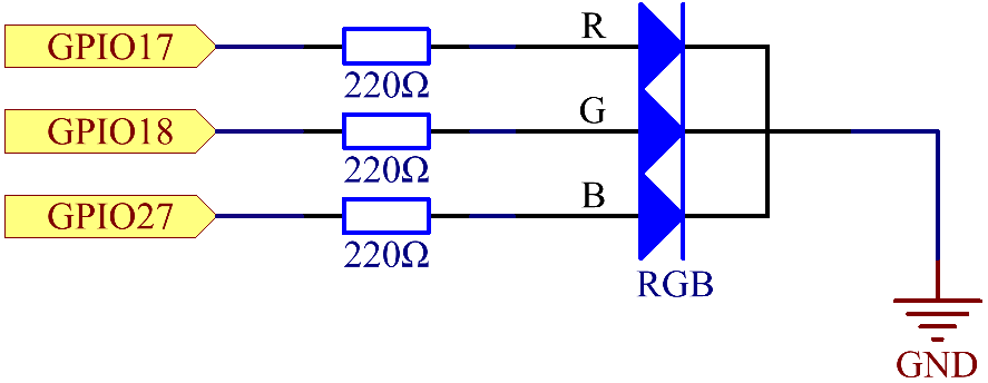
Functionality
The RGB LED can produce a wide range of colors by mixing different intensities of Red, Green, and Blue. By adjusting the power to each pin, various colors can be produced. For instance:
-
Red: Power the Red pin while keeping Green and Blue off.
-
Green: Power the Green pin while keeping Red and Blue off.
-
Blue: Power the Blue pin while keeping Red and Green off.
-
Yellow: Power both Red and Green pins while keeping Blue off.
-
Cyan: Power both Green and Blue pins while keeping Red off.
-
Magenta: Power both Red and Blue pins while keeping Green off.
-
White: Power all three pins
Testing
Use the below commands to test the component.
$ curl http://localhost:8080/rgb/ledOn-
/ledOn- turns on RGB LED -
/ledOff- turns off RGB LED -
/setRed/{val}- sets value of red to {val} -
/setRed/{val},{frequency}- sets value of red to {val} and frequency to {frequency} -
/setGreen/{val}- sets value of green to {val} -
/setGreen/{val},{frequency}- sets value of green to {val} and frequency to {frequency} -
/setBlue/{val}- sets value of blue to {val} -
/setBlue/{val},{frequency}- sets value of blue to {val} and frequency to {frequency} -
/setColor/{redVal},{greenVal},{blueVal}-
sets values of red {redVal}, green {greenVal}, and blue {blueVal}
-
-
/setColor/{redVal},{greenVal},{blueVal},{frequency1},{frequency2},{frequency3}-
sets values of red {redVal}, green {greenVal}, and blue {blueVal}, and frequencies of red {frequency1}, green {frequency2}, and {frequency3}
-
-
/setColorHex/{hexValue}- sets color value using its hex value {hexValue} -
/setColorHex/{hexValue},{frequency1},{frequency2},{frequency3}-
sets color value using its hex value {hexValue} and frequencies of red {frequency1}, green {frequency2}, and {frequency3}
-
Troubleshooting
-
LED not lighting up: Check all connections, ensure the LED is placed correctly, and check the power source.
-
Only one color is working: One of the pins might have a loose connection. Verify each color pin’s connection.
-
LED is too dim: The resistor value might be too high. Ensure you’re using 220Ω or adjust according to your power source and LED specifications
Note: The Hex value format must start with "0x" not "#" while passing it as a parameter of "setColorHex()" method. For example, use "0x0000ff" for blue.
YAML Configuration
A BCM numbering system is used. More info can be found here.
The order for declaring pins for a RGB LED component in the application.yaml file is as follows
RED-PIN-INFO, GREEN-PIN-INFO, BLUE-PIN-INFO
So in the case of
multi-pwm:
  rgb-led:
    name: RGB LED
    addresses: 17, 18, 27
    pwmTypes: SOFTWARE, SOFTWARE, SOFTWARE
    provider: pigpio-pwm
    initials: 0, 0, 0
    shutdowns: 0, 0, 0
  rgb-led-2:
    name: RGB LED 2
    addresses: 18, 27, 22
    pwmTypes: SOFTWARE, SOFTWARE, SOFTWARE
    provider: pigpio-pwm
    initials: 0, 0, 0
    shutdowns: 0, 0, 0
the red pin would be the one connected to GPIO 17, green to GPIO 18, and blue to GPIO 27. All lists of values for RGB LED components will follow the same order.
Constructor and Methods
To see the constructor and methods of our RGBLEDHelper class see our javadoc here for more details.
An Example Controller
@Controller("/rgb")
public class rgbController {
    private final RGBLEDHelper rgbledHelper;

    public rgbController(@Named("rgb-led") MultiPinConfiguration rgbLed){
        this.rgbledHelper = new RGBLEDHelper(rgbLed);
    }

    @Get("/setRed/{val}")
    public void setRed(String val){
        rgbledHelper.setRed(Integer.parseInt(val));
    }

    @Get("/setRed/{val},{frequency}")
    public void setRed(String val, String frequency){
        rgbledHelper.setRed(Integer.parseInt(val), Integer.parseInt(frequency));
    }

    @Get("/setBlue/{val}")
    public void setBlue(String val){
        rgbledHelper.setBlue(Integer.parseInt(val));
    }

    @Get("/setBlue/{val},{frequency}")
    public void setBlue(String val, String frequency){
        rgbledHelper.setBlue(Integer.parseInt(val), Integer.parseInt(frequency));
    }

    @Get("/setGreen/{val}")
    public void setGreen(String val){
        rgbledHelper.setGreen(Integer.parseInt(val));
    }

    @Get("/setGreen/{val},{frequency}")
    public void setGreen(String val, String frequency){
        rgbledHelper.setGreen(Integer.parseInt(val), Integer.parseInt(frequency));
    }

    @Get("/setColor/{redVal},{greenVal},{blueVal}")
    public void setColor(int redVal, int greenVal, int blueVal){
        int[] colors = new int[] {redVal, greenVal, blueVal};
        rgbledHelper.setColor(colors);
    }

    @Get("/setColor/{redVal},{greenVal},{blueVal},{frequency1},{frequency2},{frequency3}")
    public void setColor(int redVal, int greenVal, int blueVal, int frequency1, int frequency2, int frequency3){
        int[] colors = new int[] {redVal, greenVal, blueVal};
        int[] frequency = new int[] {frequency1, frequency2, frequency3};
        rgbledHelper.setColor(colors, frequency);
    }

    @Get("/setColorHex/{hexValue}")
    public void setColorHex(String hexValue) {
        rgbledHelper.setColorHex(hexValue);
    }

    @Get("/setColorHex/{hexValue},{frequency1},{frequency2},{frequency3}")
    public void setColorHex(String hexValue, int frequency1, int frequency2, int frequency3) {
        int[] frequency = new int[] {frequency1, frequency2, frequency3};
        rgbledHelper.setColorHex(hexValue, frequency);
    }

    @Get("/ledOff")
    public void ledOff() {
        rgbledHelper.ledOff();
    }

    @Get("/ledOn")
    public void ledOn() {
        rgbledHelper.ledOn();
    }
}
4.3.10. Servo Motor
Overview
This section provides details of the Servo Motor. Specifically, the Micro Servo 9G - SG90, which is a positional servo with a range from 0 to 180 degrees. These details include the components and assembly instructions.
Components
-
1 x RaspberryPi
-
1 x Breadboard
-
1 x T-extension Board
-
1 x Servo-Motor
-
3 x Jumper Wires
-
Power source (appropriate voltage, typically 3.3V)
Assembly Instructions
-
Connect a jumper wire to 3.3V
-
Connect a jumper wire to GPIO 18
-
Connect a jumper wire to GND
-
Connect the 3.3V jumper wire to the SIG pin (Color: Red)
-
Connect the GND jumper wire to the GND pin (Color: Brown or Black)
-
Connect the GPIO 18 jumper wire to the VCC pin (Color: Orange)


Functionality
Servo motor is a PWM type and will rotate the arm between the angles of 0 to 180 degrees.
Testing the Circuit
Use the below commands to test the component.
$curl http://localhost:8080/servoMotor/enable-
/enable- Turns the Servo Motor on.
$curl http://localhost:8080/servoMotor/disable-
/disable- Turns the Servo Motor off.
$curl http://localhost:8080/servoMotor/setAngle/{angle}-
/setAngle/{angle}- Sets the indicated angle for the Servo Motor.
Troubleshooting
-
Servo Motor not rotating:
-
Verify that all wires are placed into the correct locations on the Breadboard
-
Verify that the wires are placed correctly into the wire receiver for the Servo Motor
-
Verify that the Servo Motor is enabled
-
YAML Configuration
A BCM numbering system is used. More info can be found here.
pwm:
 servo-motor:
      name: Servo Motor
      address: 18
      pwmType: SOFTWARE
      provider: pigpio-pwm
      initial: 0
      shutdown: 0
Constructor and Methods
The constructor and the methods within the ServoMotorHelper class can be seen in our javadoc here.
Example Controller
This controller uses the Servo Motor to move the arm once prompted by the commands
@Controller("/servoMotor")
public class ServoMotorController {
    private final ServoMotorHelper servoMotorHelper;

    public ServoMotorController(@Named("servo-motor")Pwm servoMotor) {
        this.servoMotorHelper = new ServoMotorHelper(servoMotor);
    }

    @Get("/enable")
    public void enableServoMotor() {
        servoMotorHelper.enable();
    }

    @Get("/disable")
    public void disableServoMotor() {
        servoMotorHelper.disable();
    }

    @Get("/setAngle/{angle}")
    public void setAngle(int angle) {
        servoMotorHelper.setAngle(angle);
    }
}